To avoid these ads, REGISTER NOW!

Super Street/ Super Gas Fairlane Build

MP&C

Well-known member
Joined
Oct 21, 2009
Messages
4,401
Location
Leonardtown, MD
Although this car is now together, and I did take a grunch of photos, I realized the other day I never had done a complete build thread on it... I had been working on bowties at the time, so by default it just didn't fit in the forums I was on. There were a few excerpts here and there to show some of the process that could help out with other makes, but not a start to finish build thread. So let's do one. Hopefully someone can pick up some tricks or tips for working on their own project.


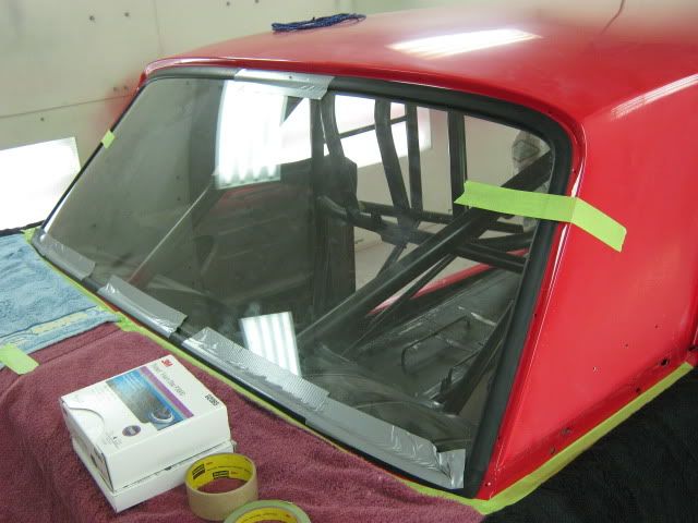
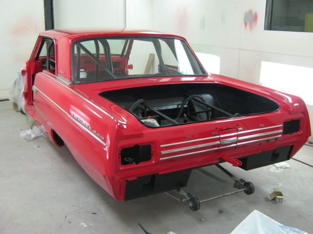
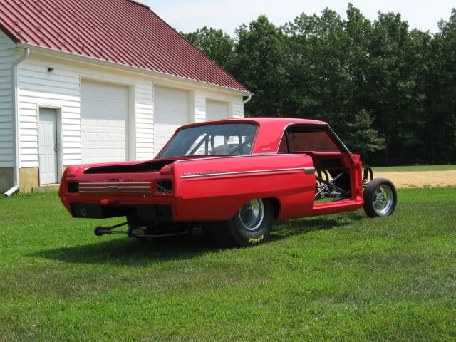
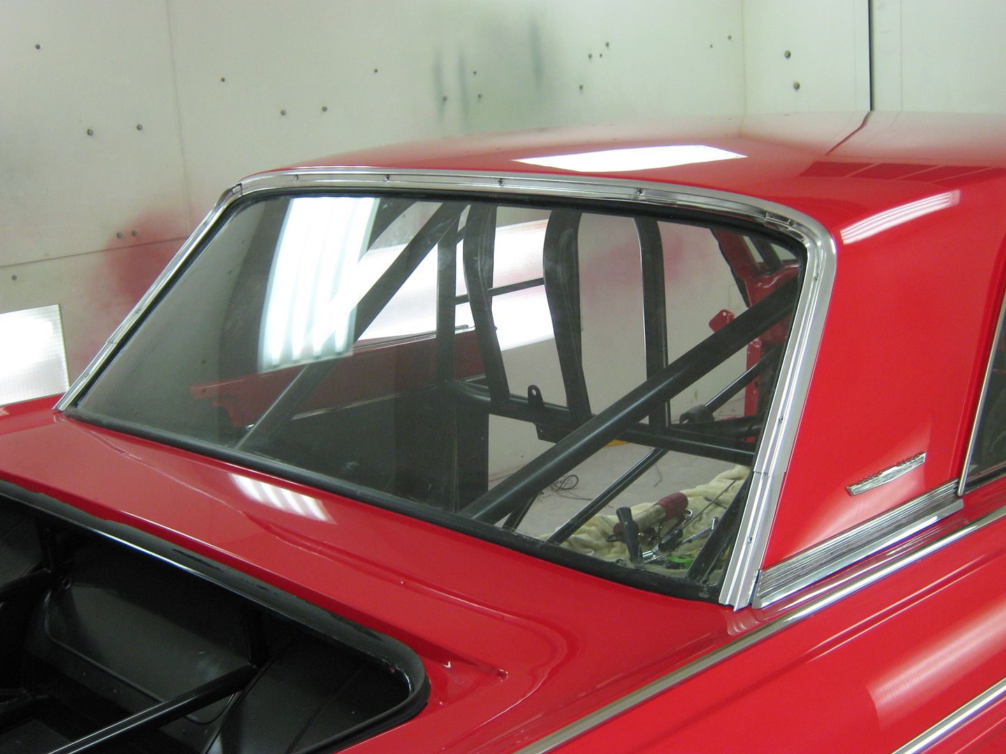
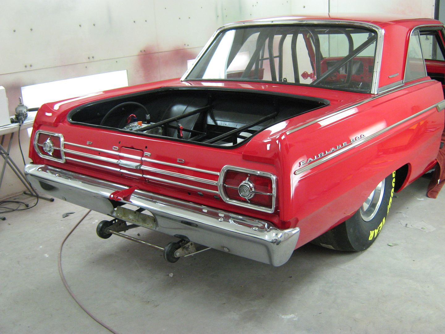
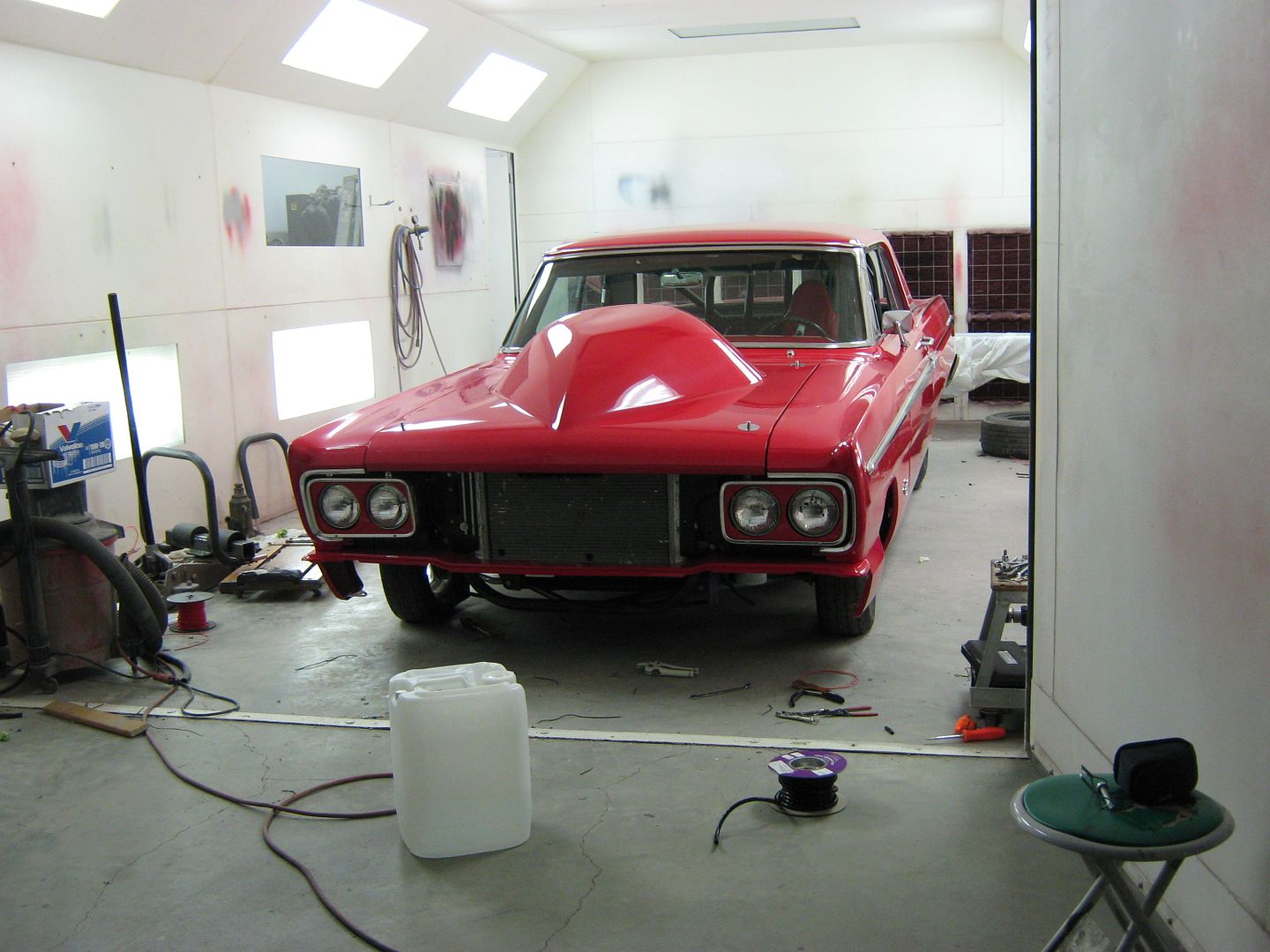
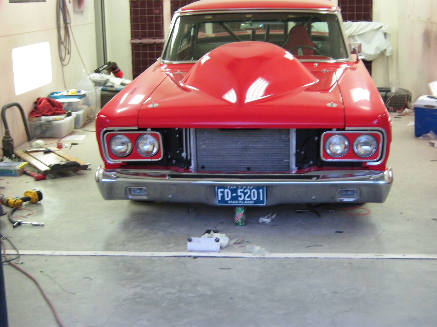
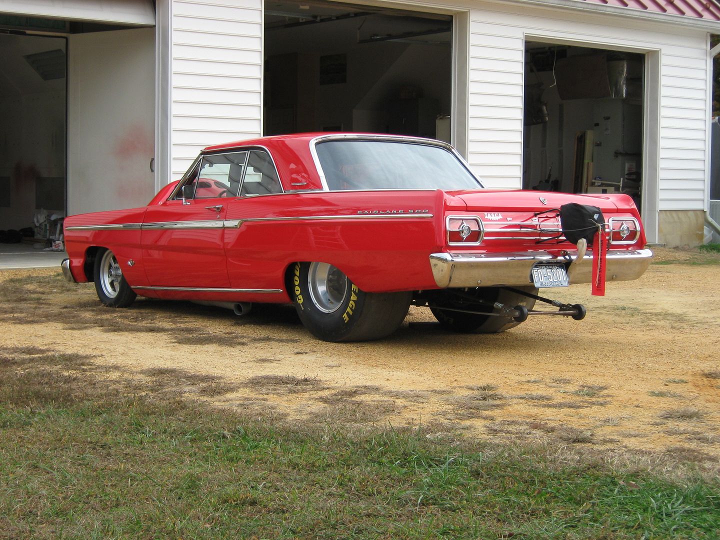
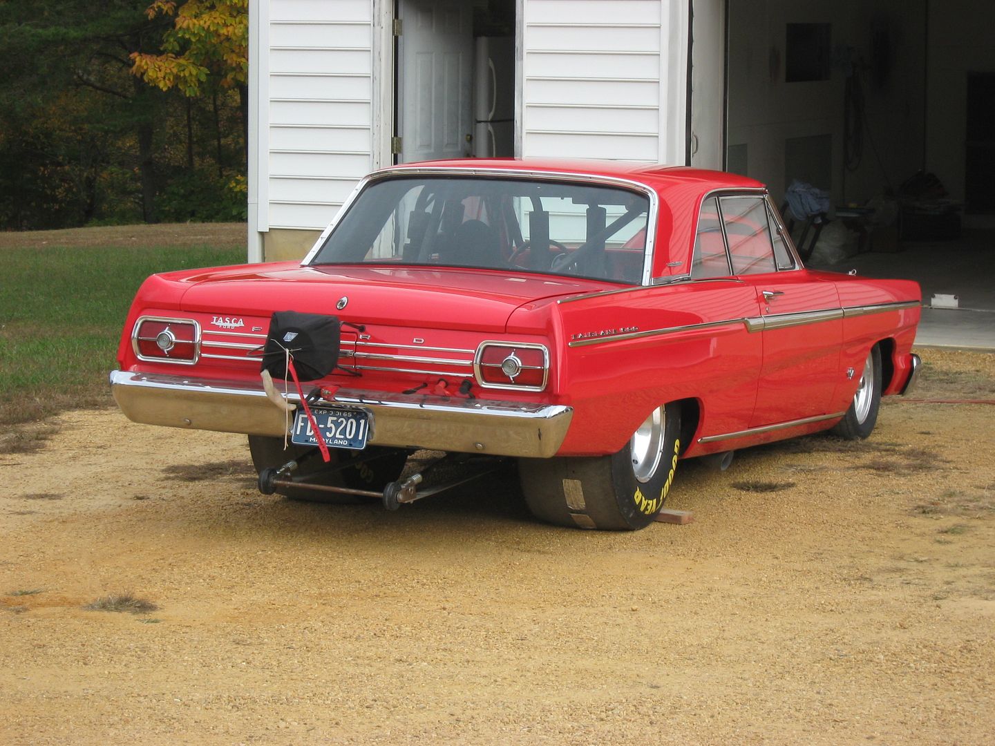
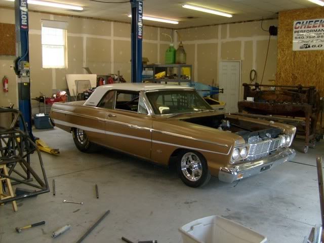
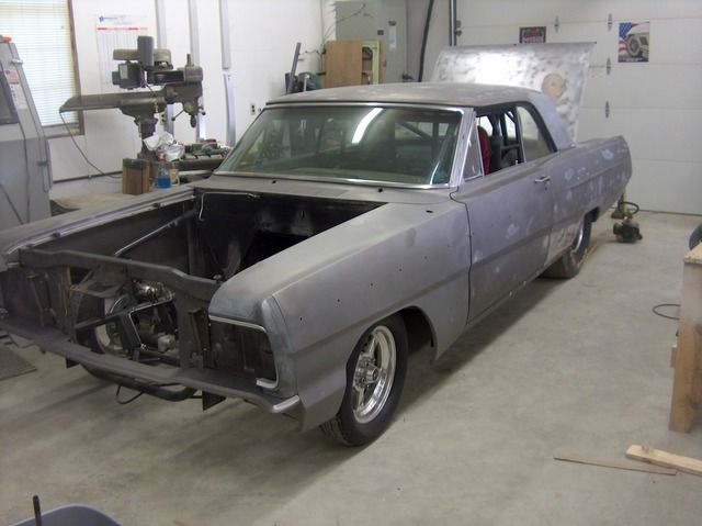
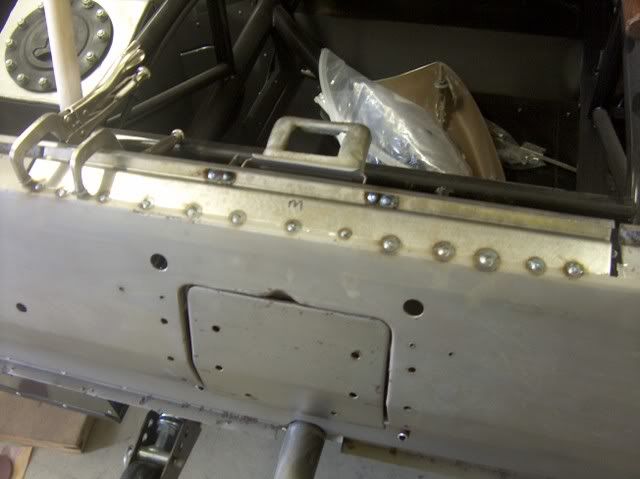
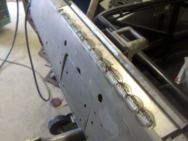
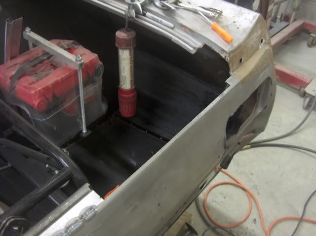
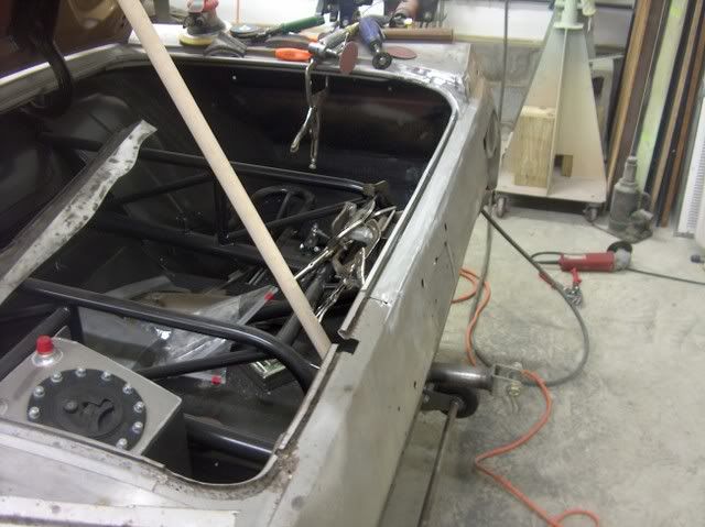
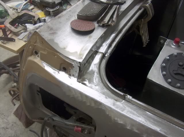
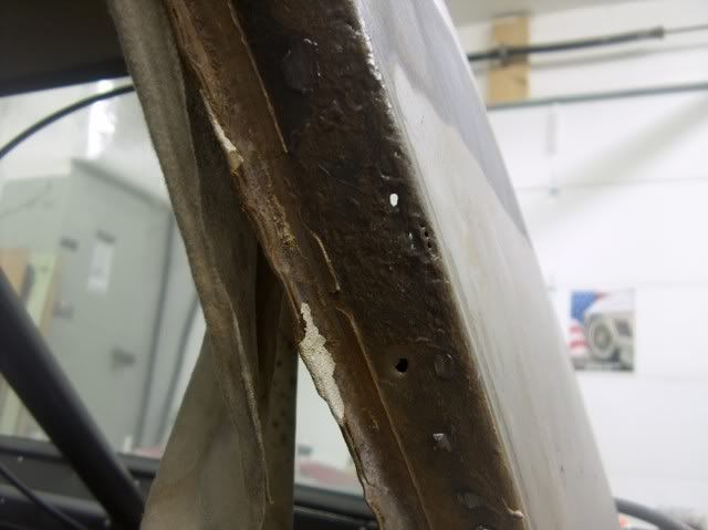
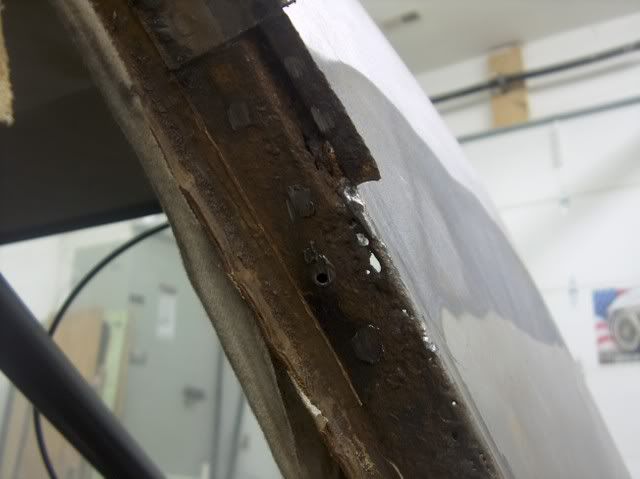
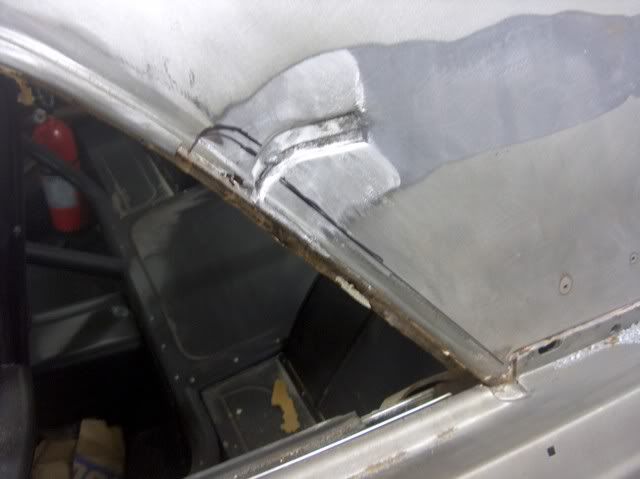
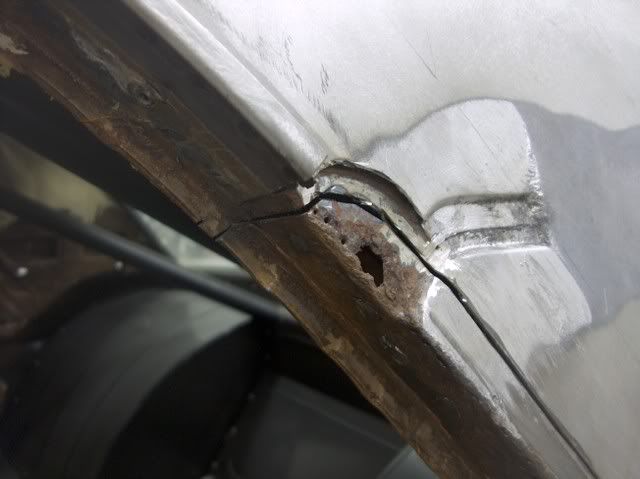
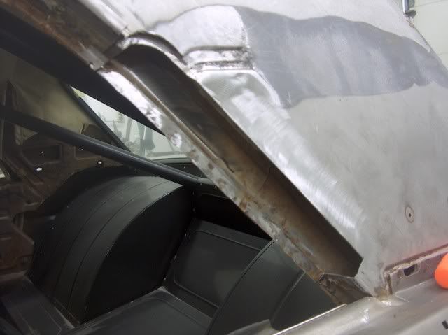
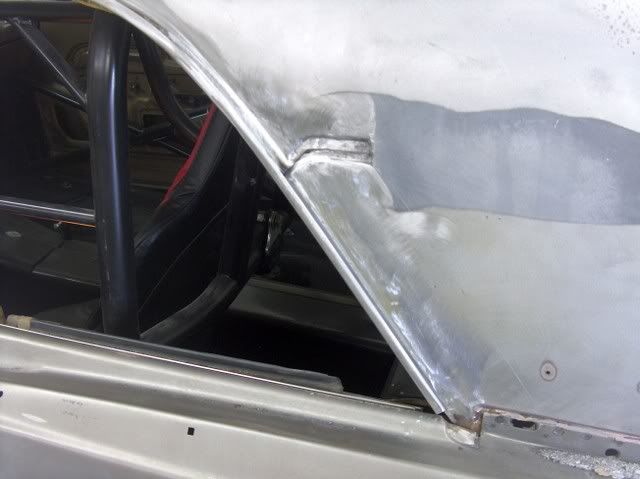
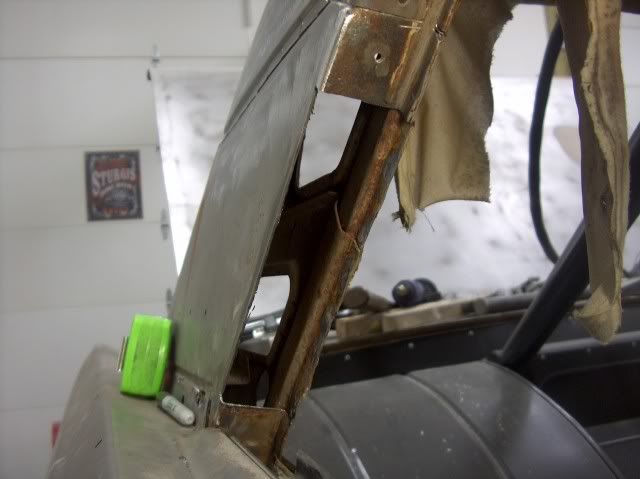
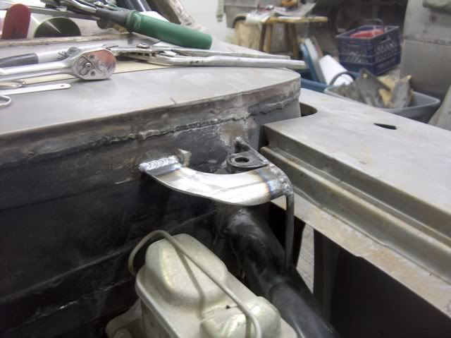
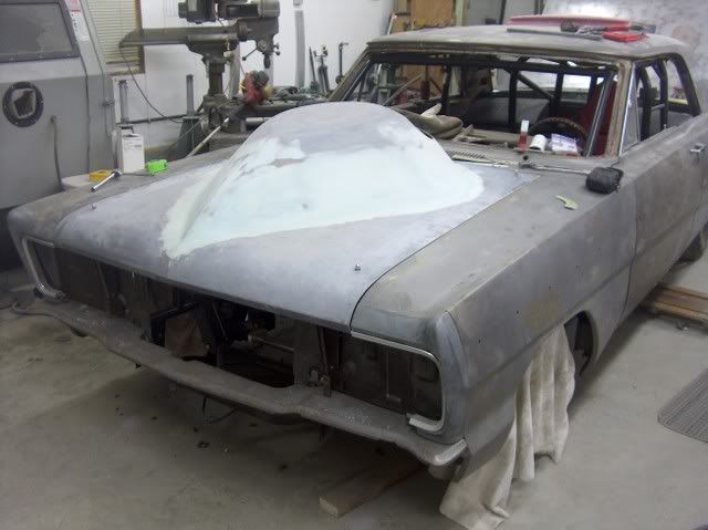
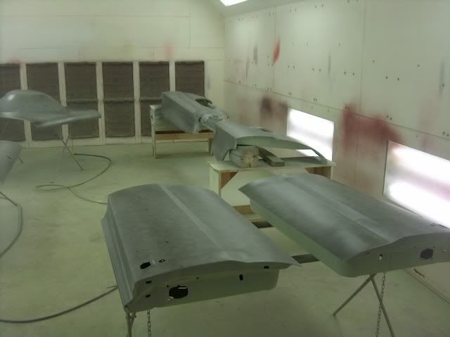
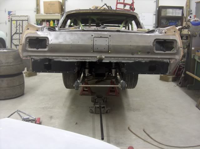
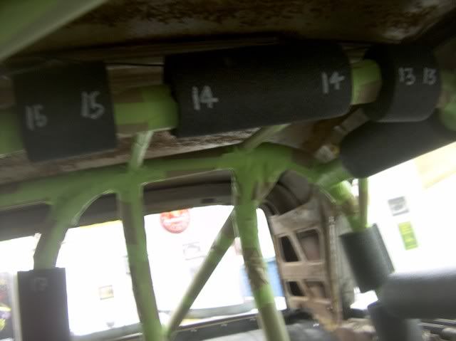
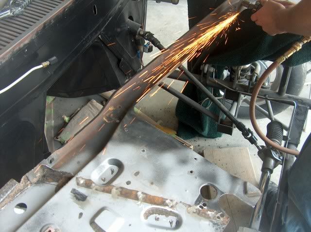
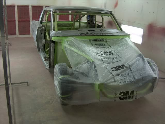
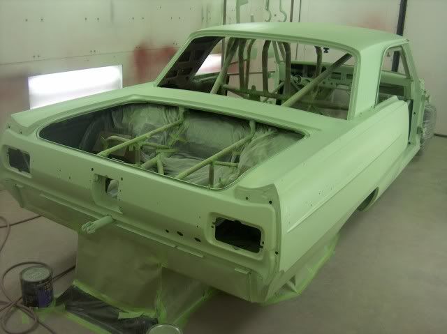
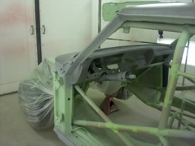
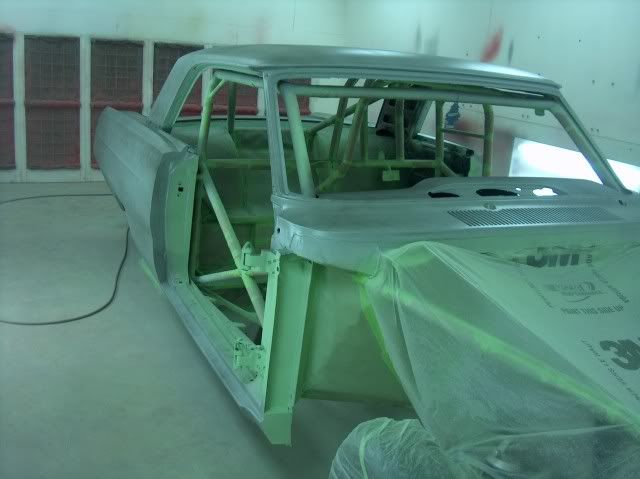
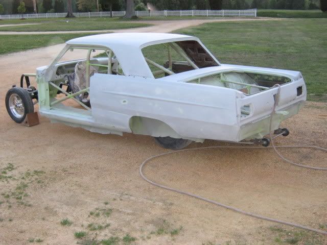
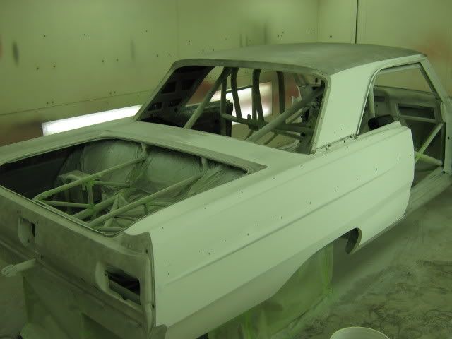
The owner first had plans for a resto-mod, but after a weekend as a spectator at the MIR drag strip, he had flashbacks of an earlier time, and the direction of the build drastically changed. A full chrome moly tube chassis was built and the body installed at Cheeks Performance in VA. And this is what I had to work with.....


S6300082.jpg


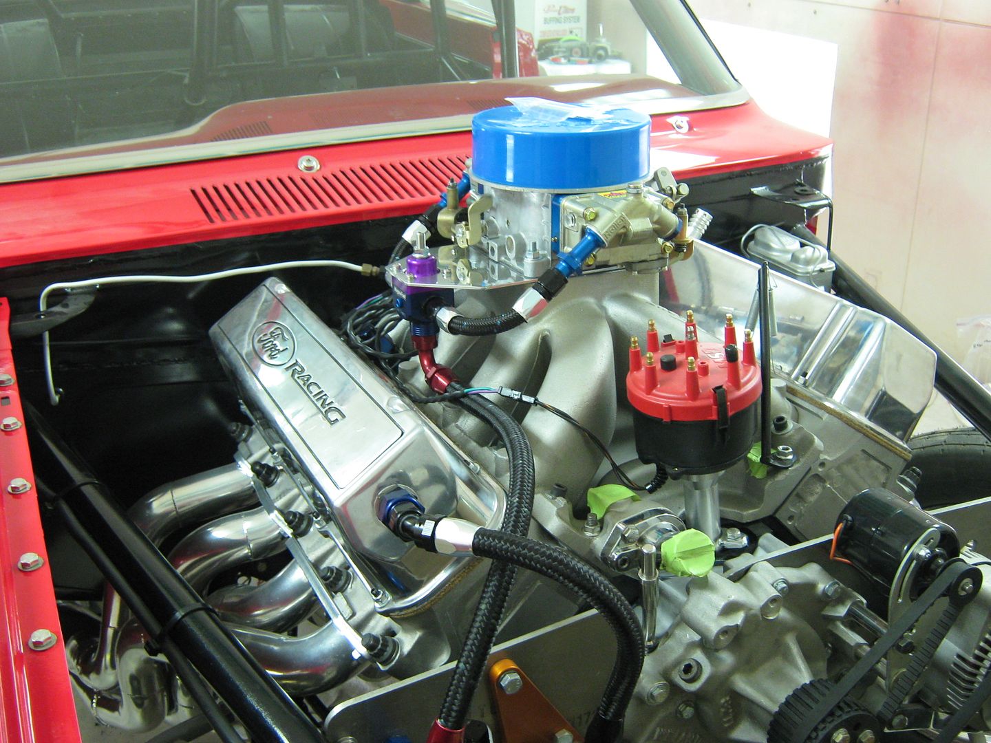
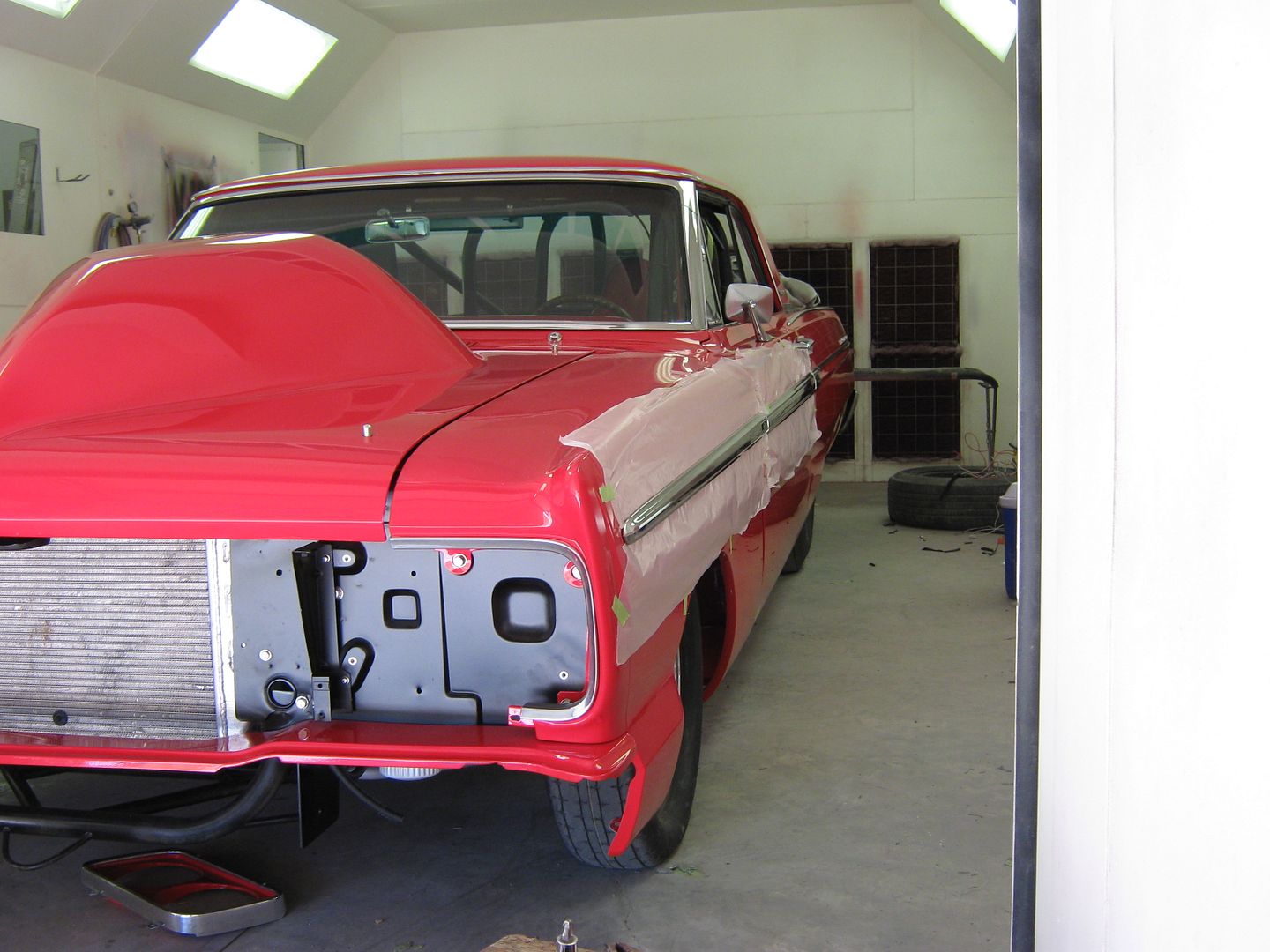
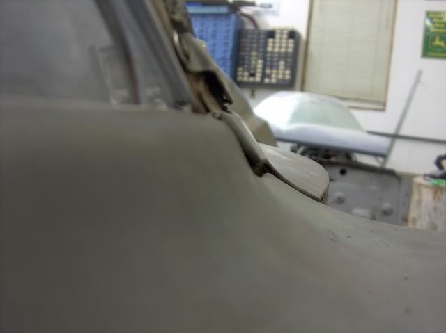
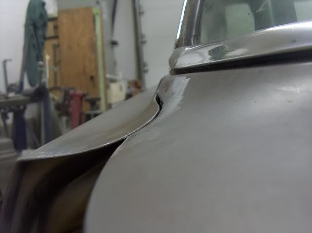
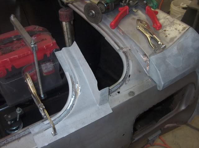
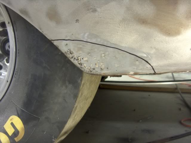
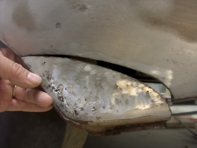
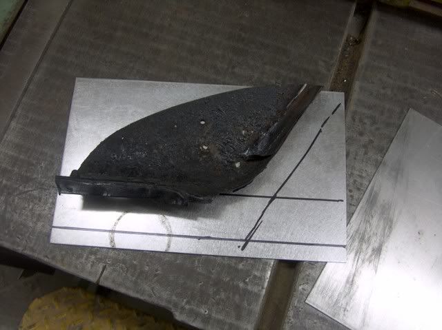
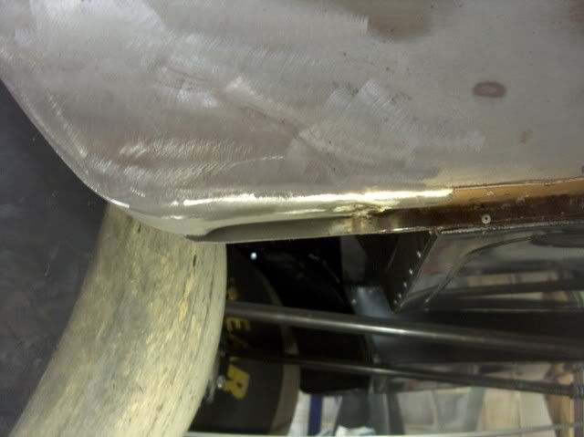
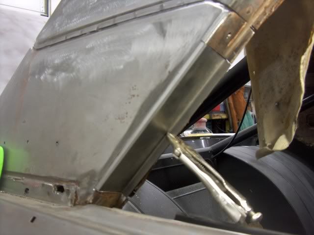
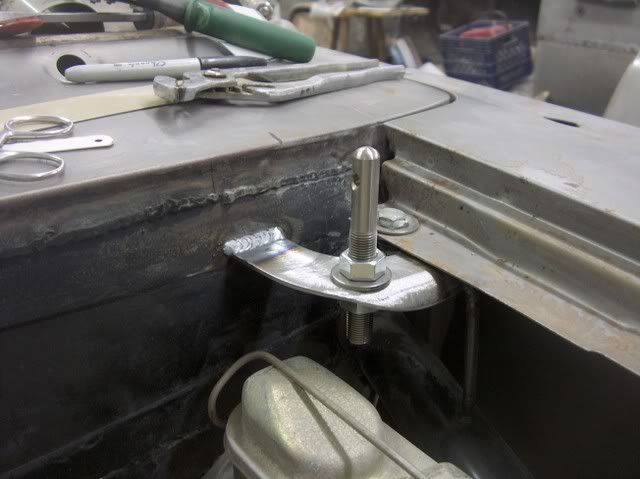
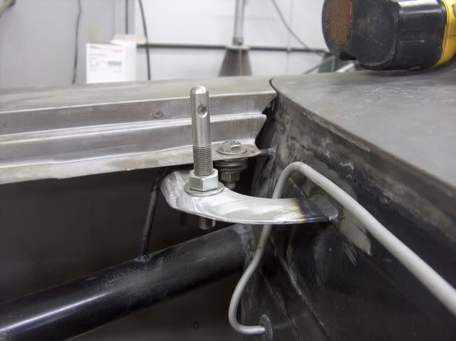
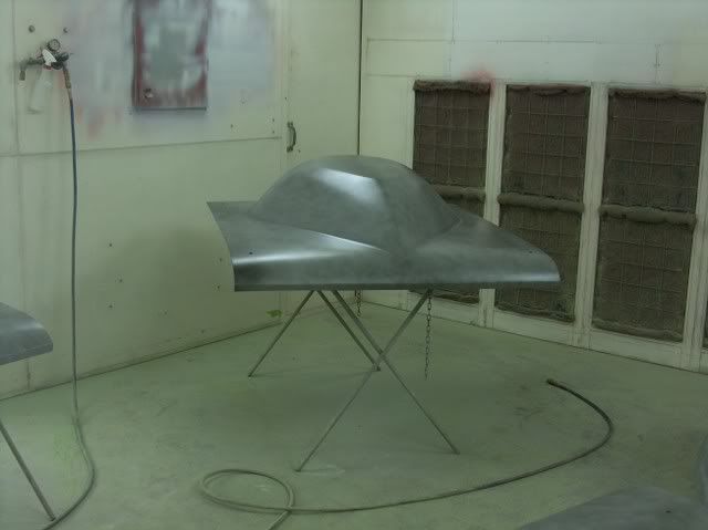
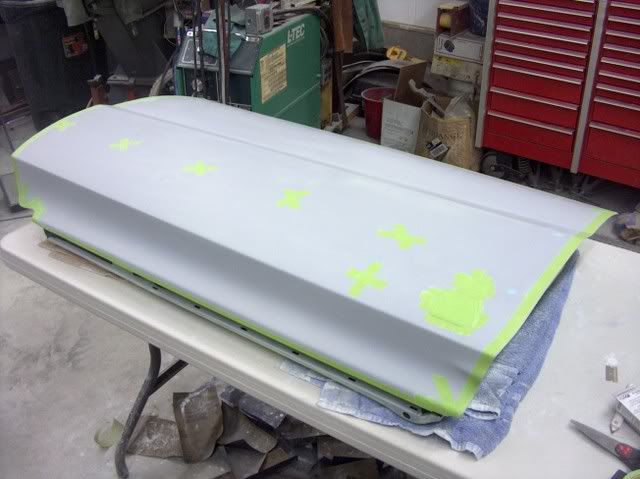
As an homage to the Thunderbolts from a year earlier, the owner had decided on a Crites teardrop hood. Only it didn't quite fit......


Picture002.jpg


Picture005.jpg


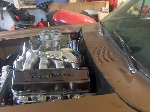
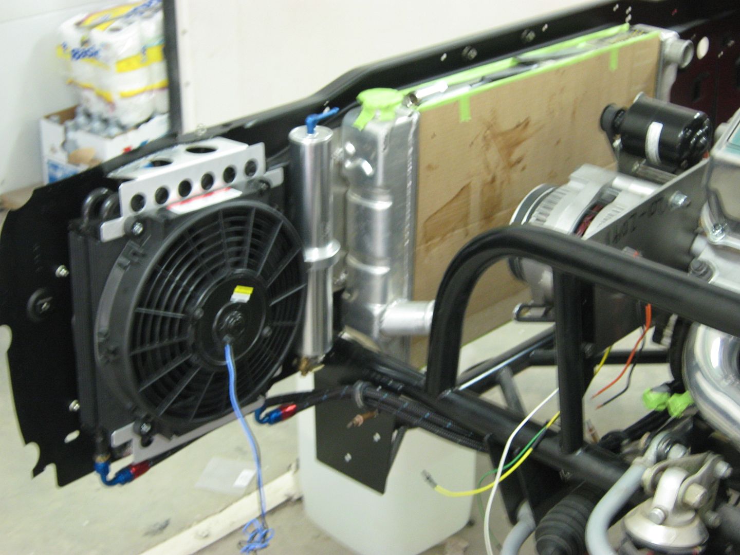
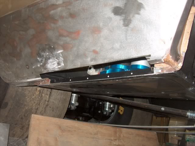
....as the engine was raised up a bit for the harmonic balancer to clear the rack and pinion. He was ready to throw in the towel and send the hood back, and concede to using a snorkel. I told him to order another teardrop, and we'd make it work. He was hesitant (I don't think he trusted me), but he did order it.


Picture017.jpg


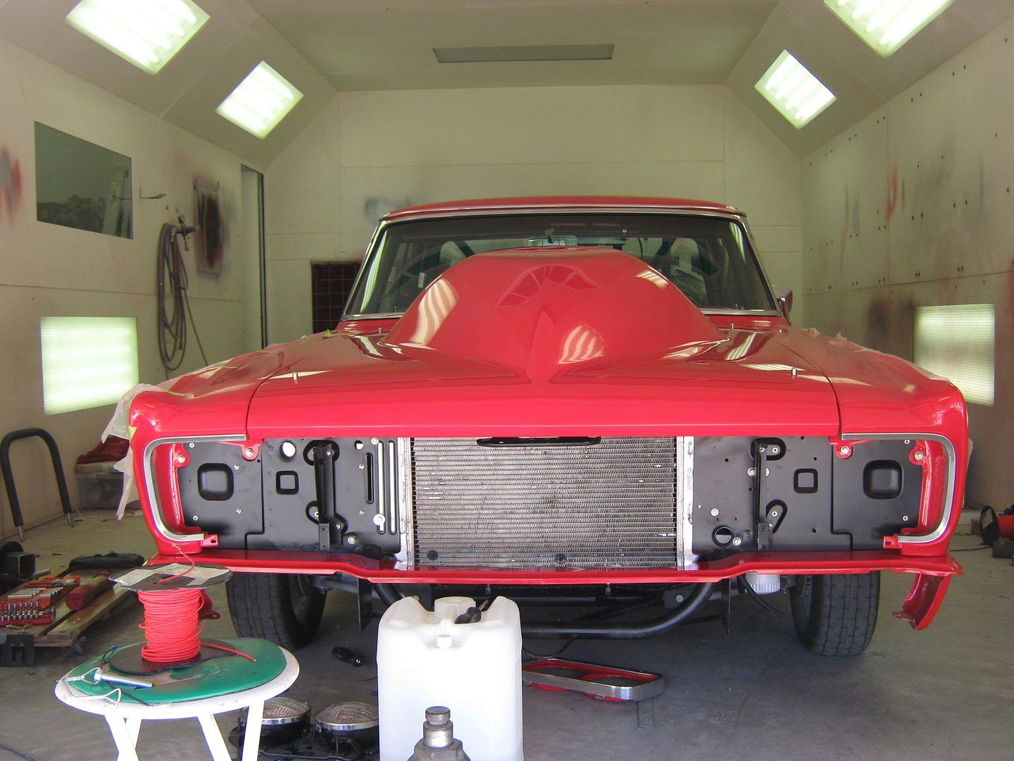
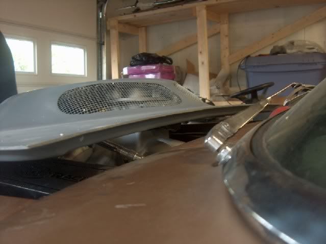
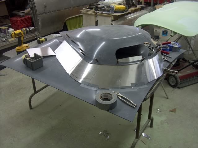
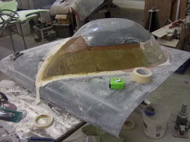
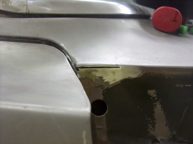
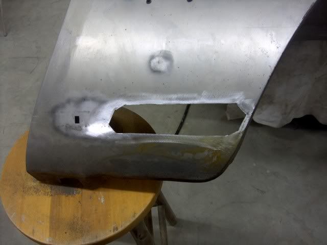
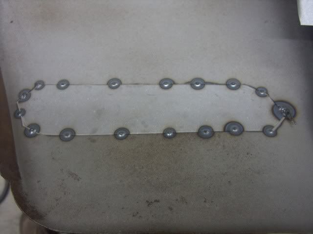
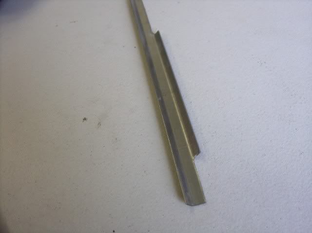
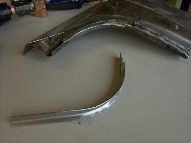
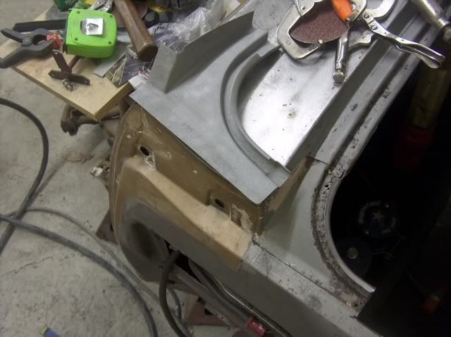
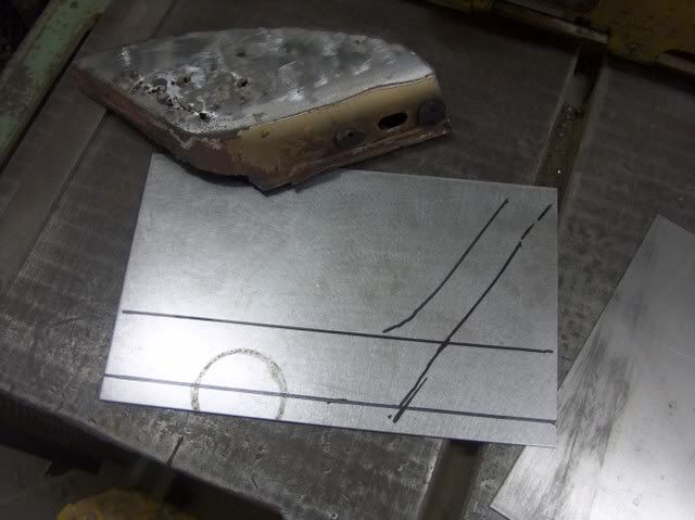
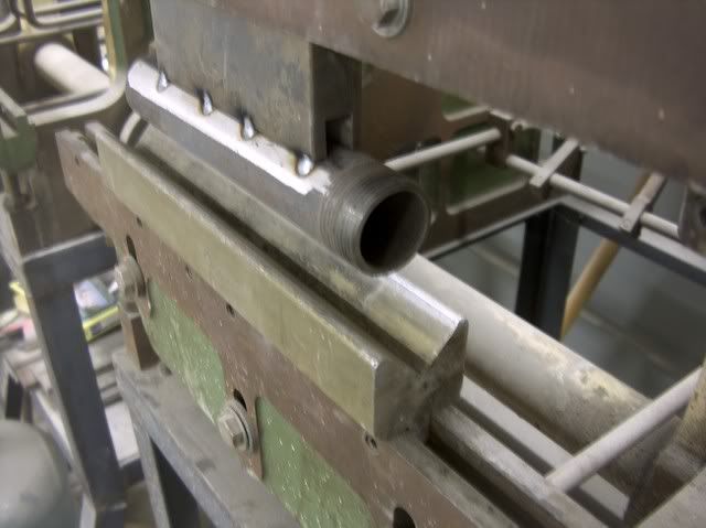
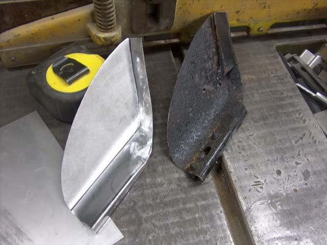
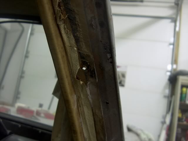
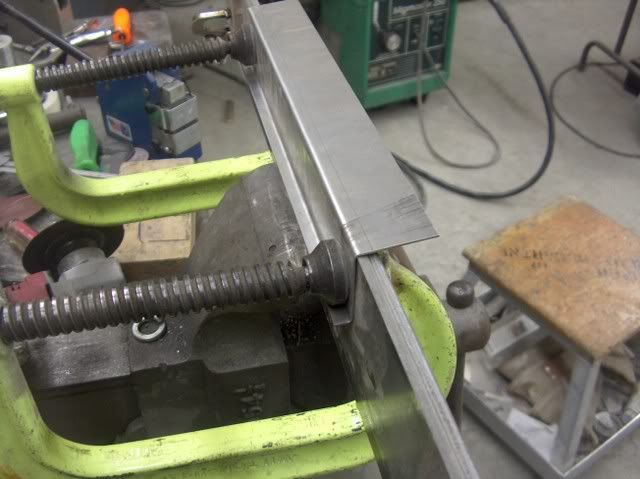
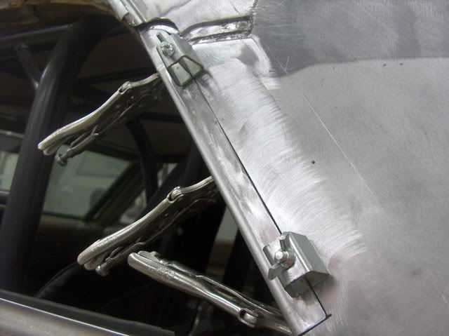
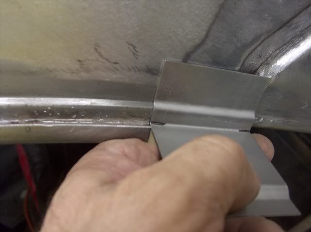
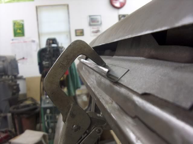
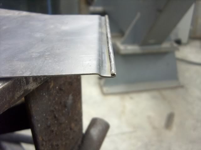
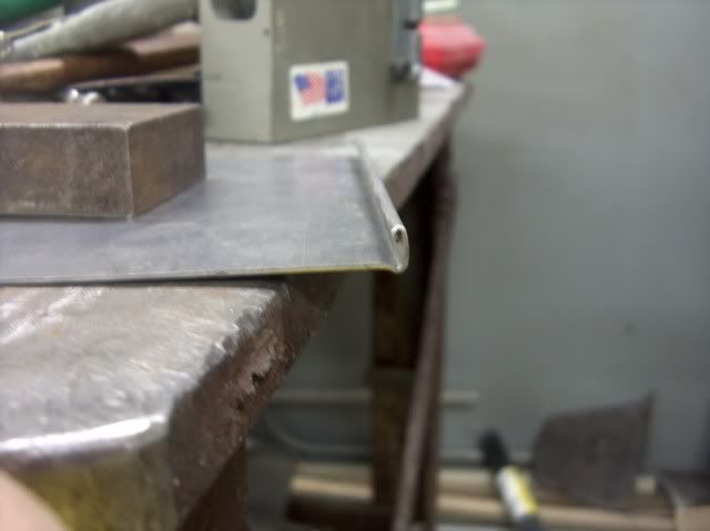
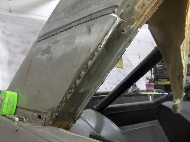
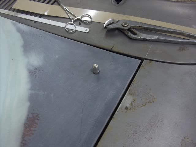
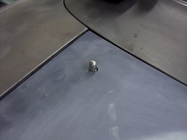
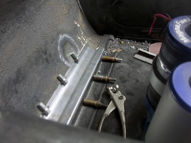
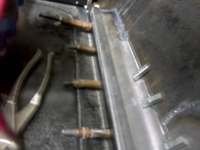
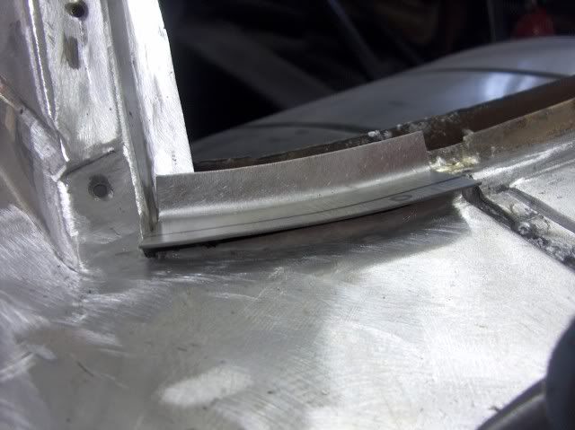
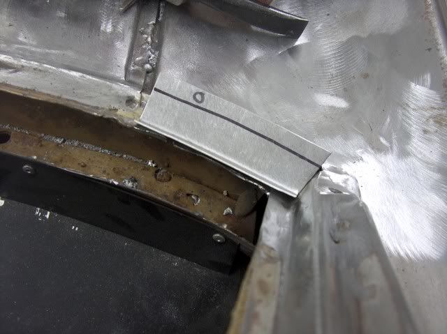
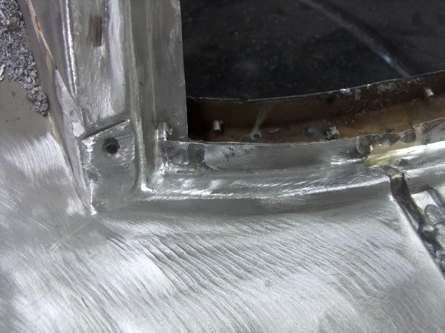
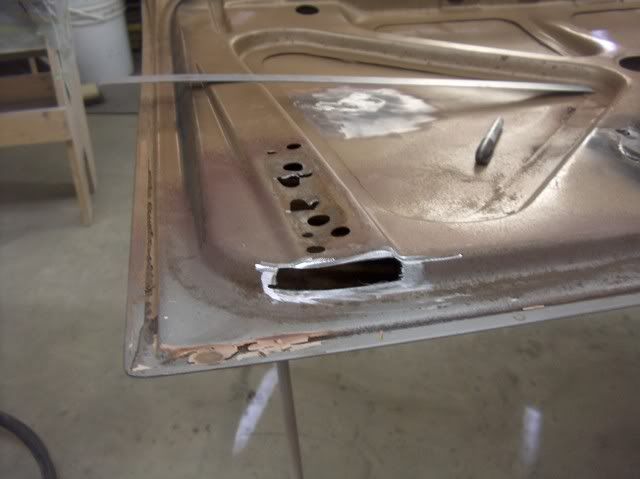
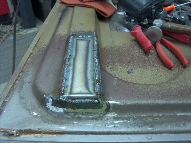
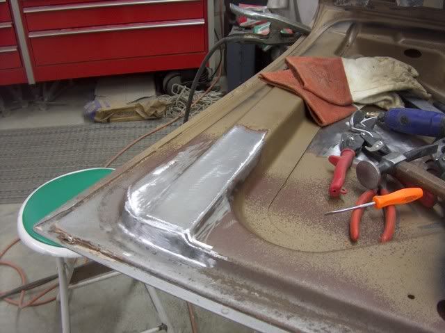
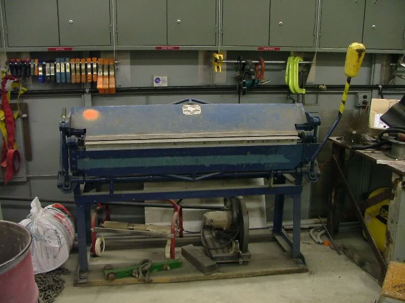
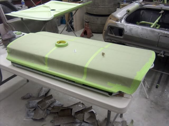
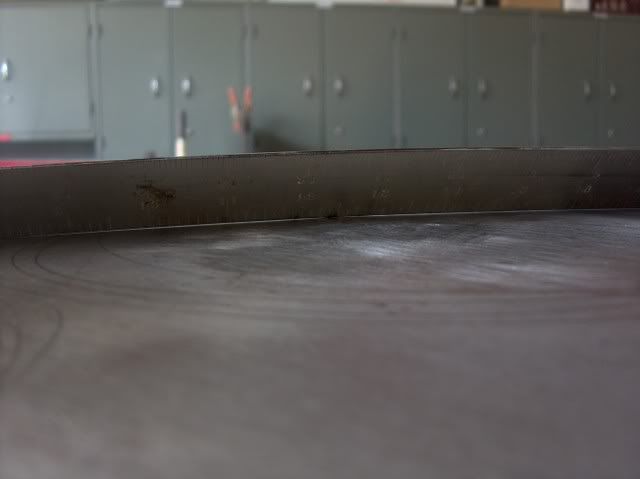
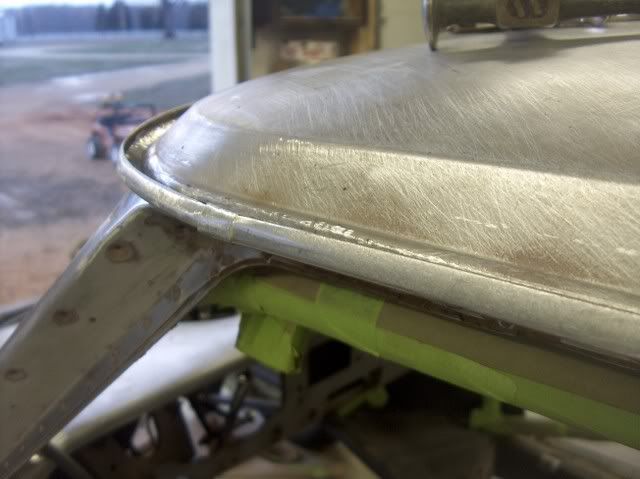
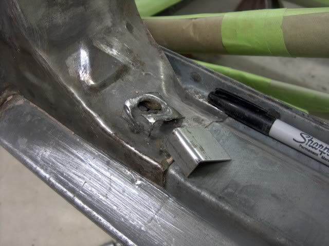
Height mocked up. The aluminum will be used to support the f/g mat while the resin cures. Then it will get flipped over, remove the aluminum, and more mat goes in from the back side. I never could get the hang of welding on fiberglass, so I had a local Corvette guy come over and join in the fun. :lol_hitti


Picture019.jpg


Picture021.jpg


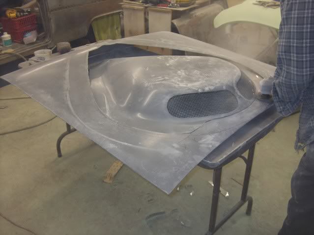
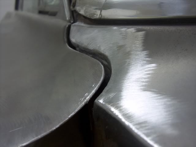
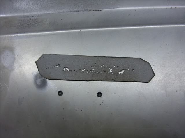
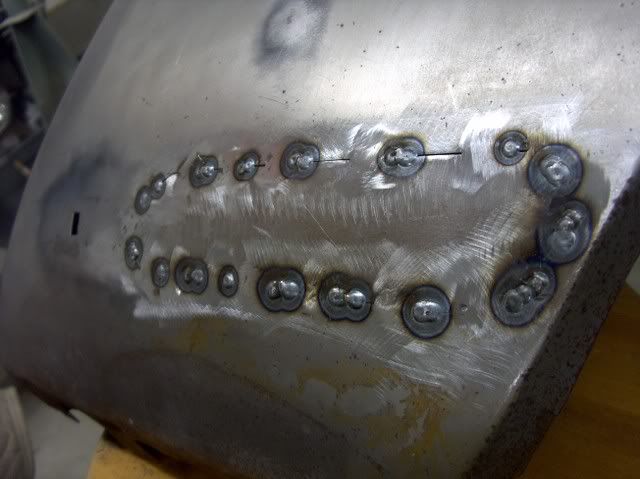
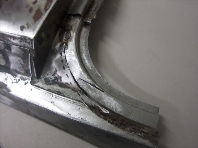
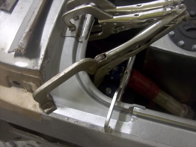
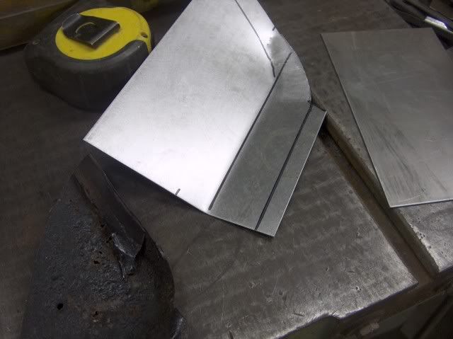
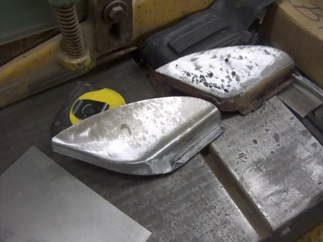
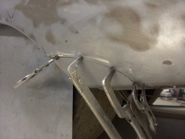
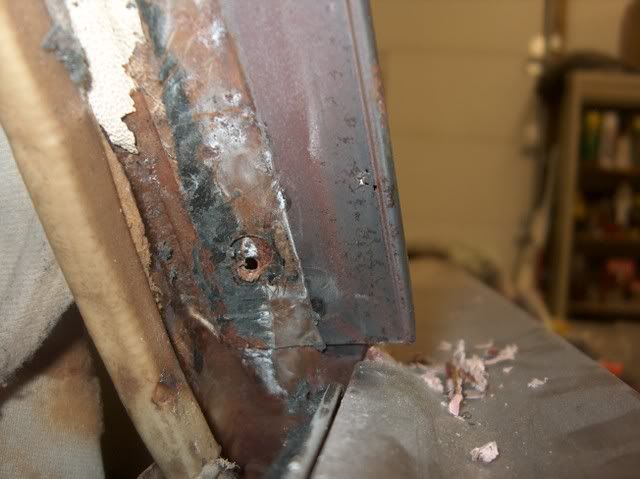
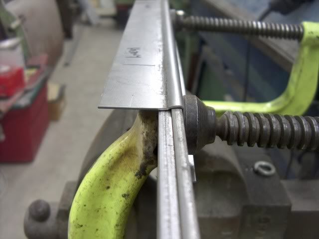
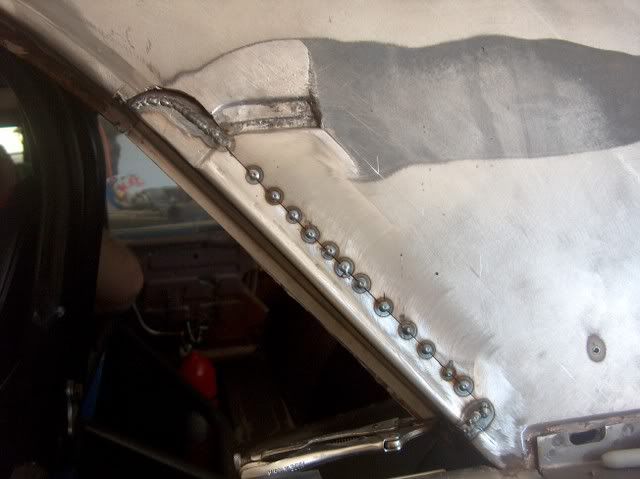
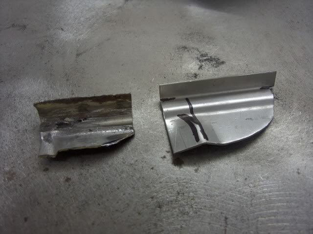
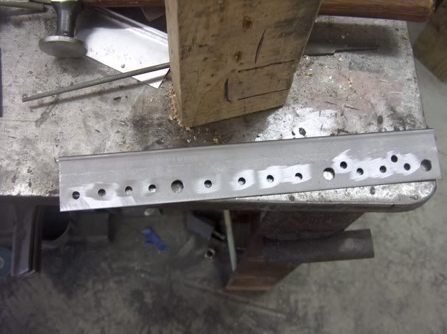
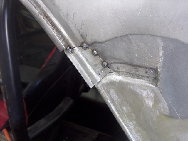
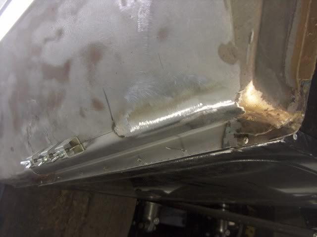
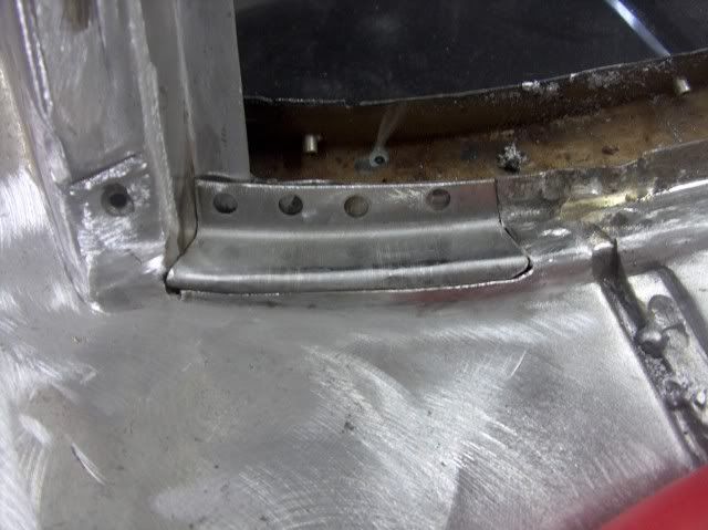
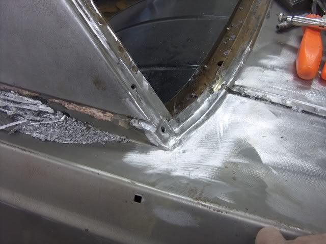
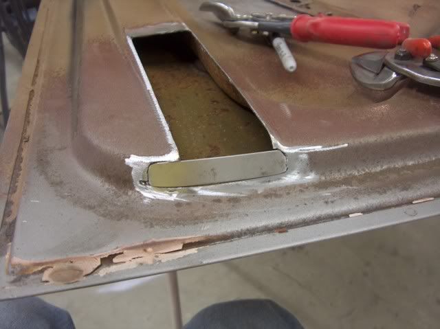
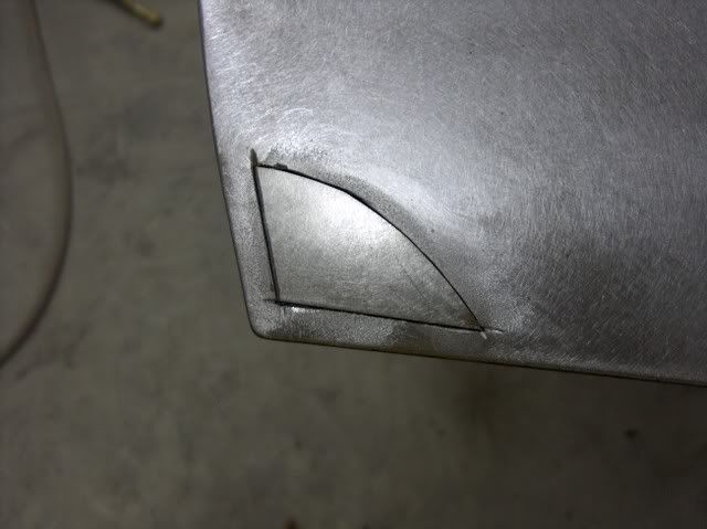
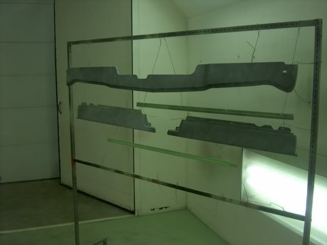
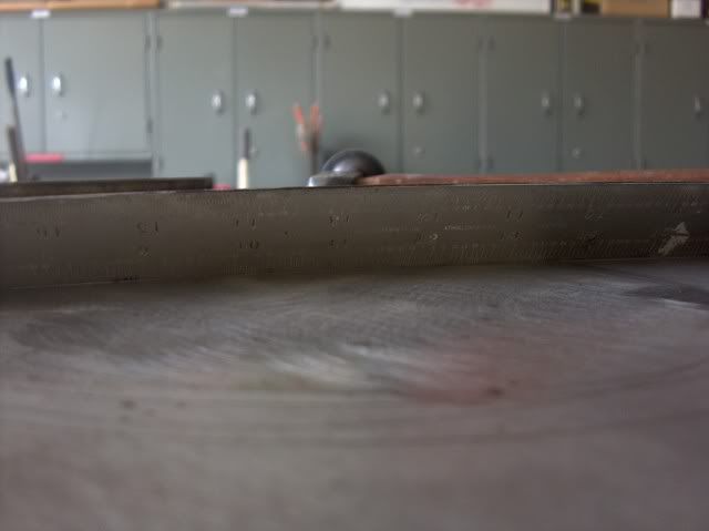
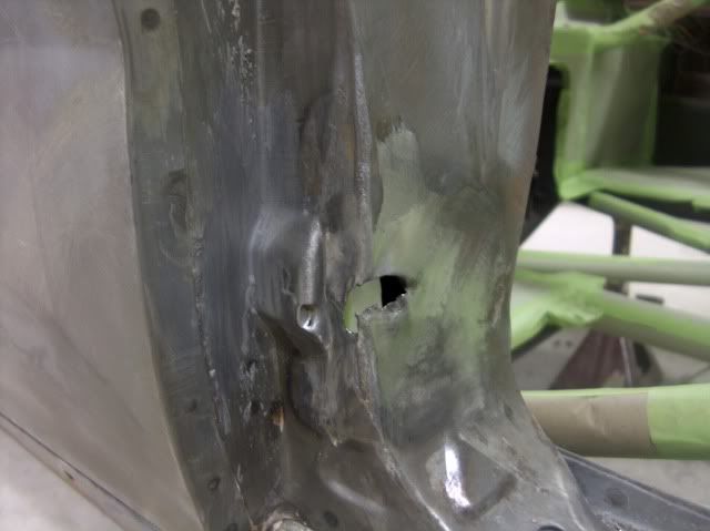
Strips of f/g mat laid in to tighten things up, and keep the hood scoop from moving.


Picture023.jpg


Picture024.jpg


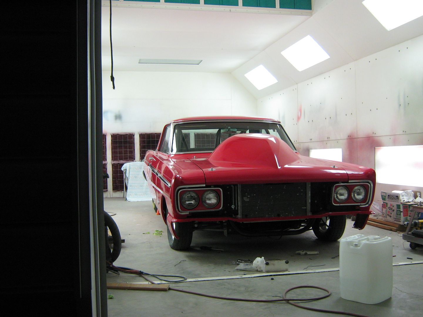
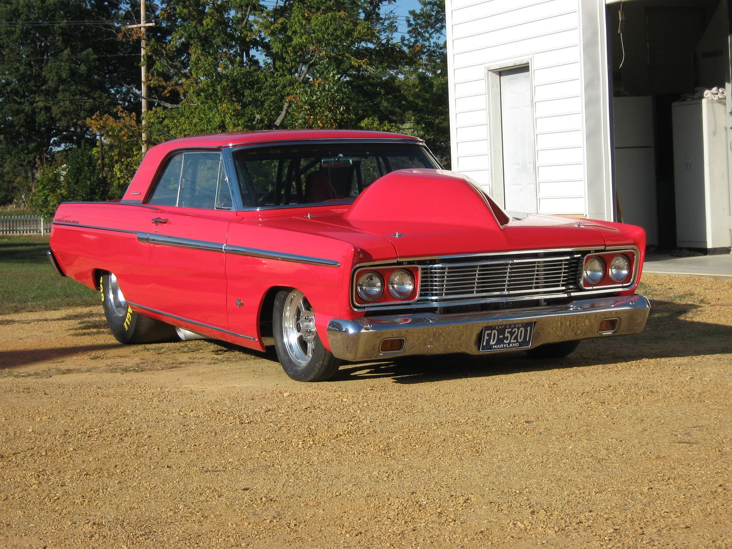
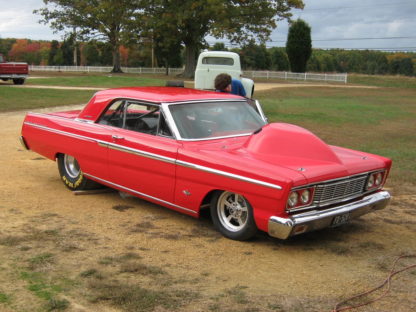
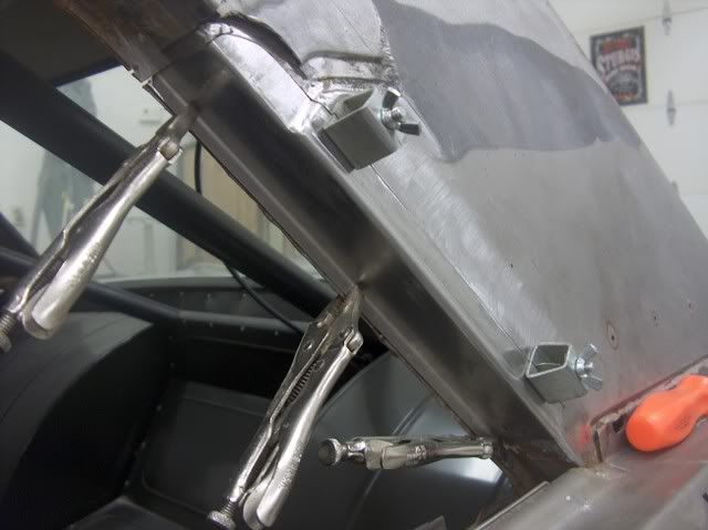
The owner did stop by and loved the look. When I gave him a hard time, he did say it wasn't that he didn't trust me, just that he couldn't see my vision. :D


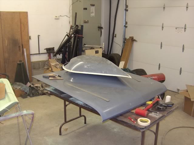
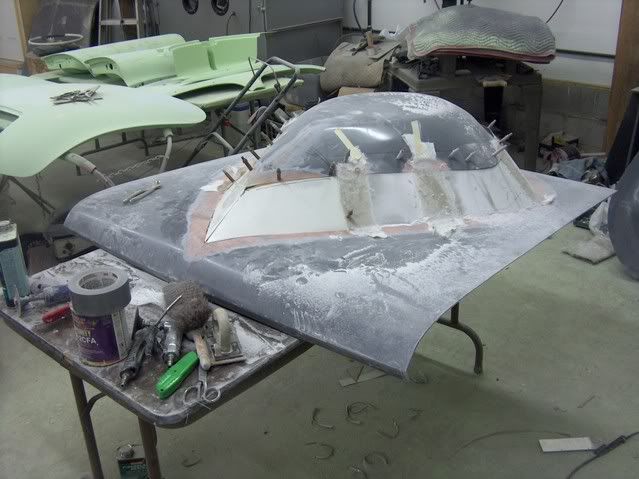
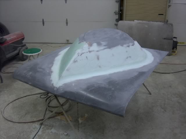
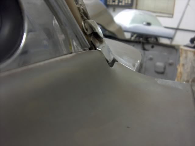
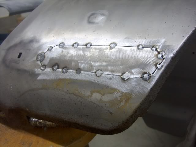
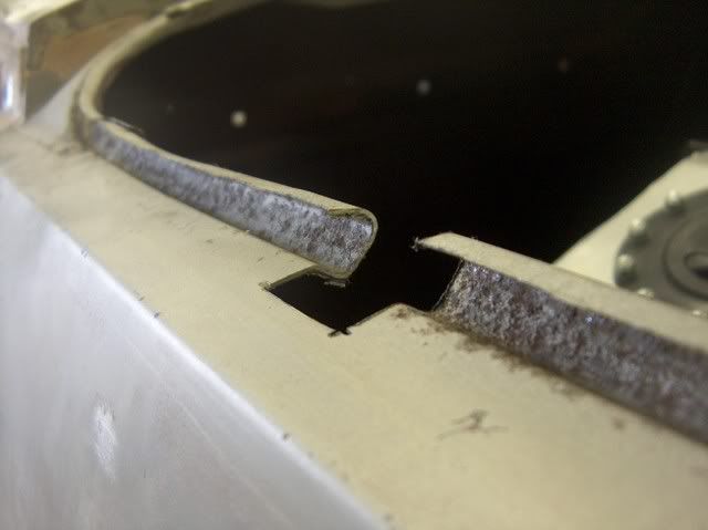
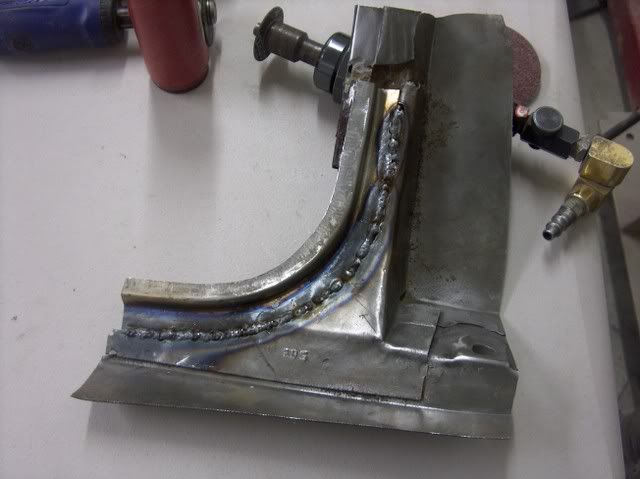
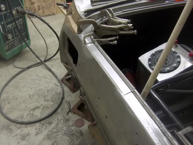
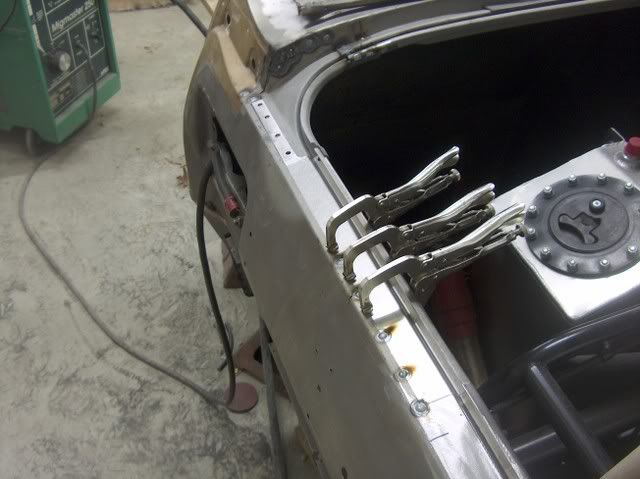
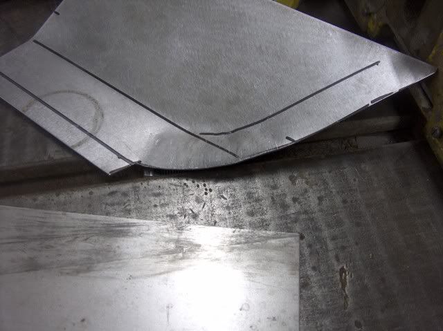
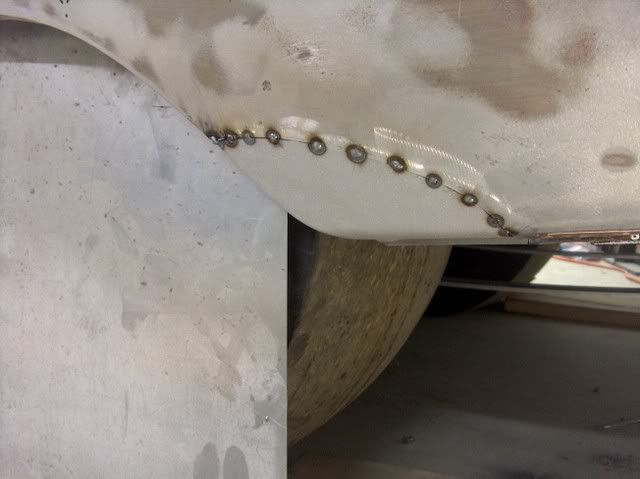
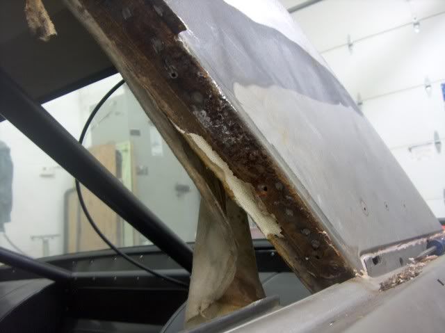
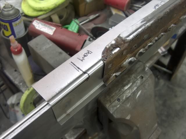
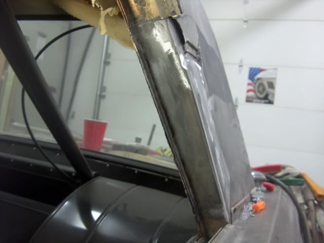
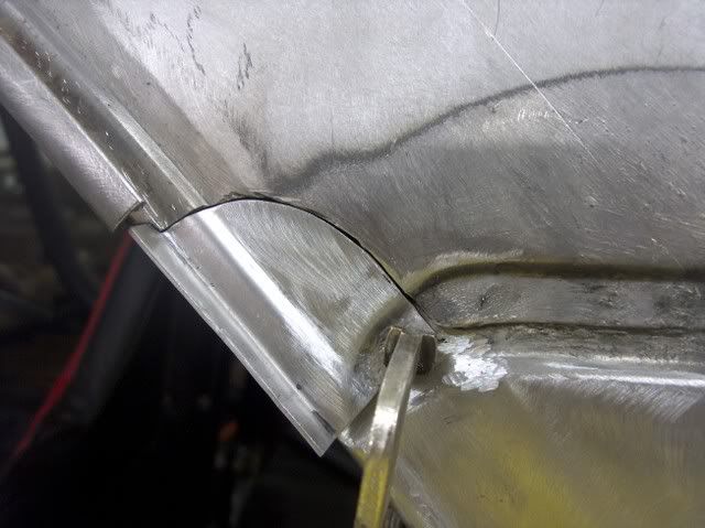
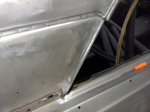
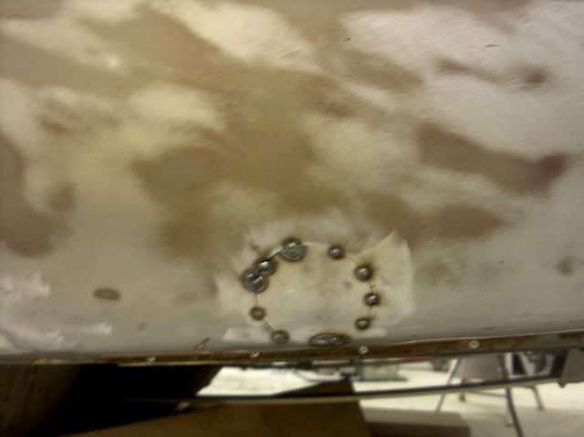
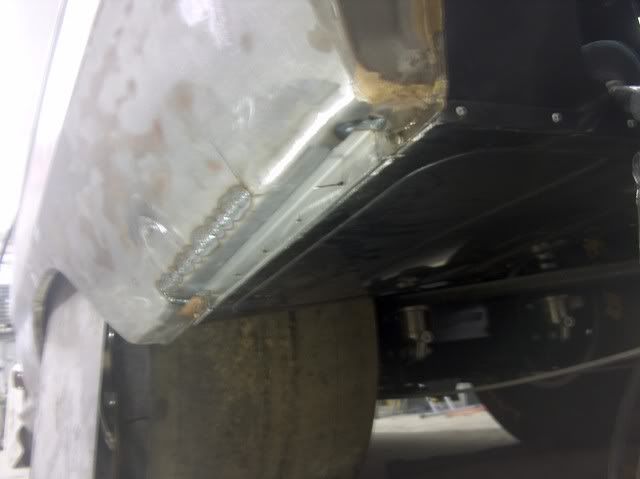
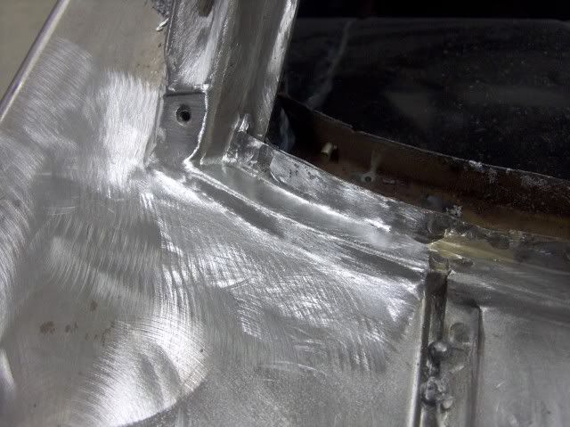
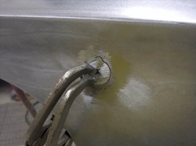
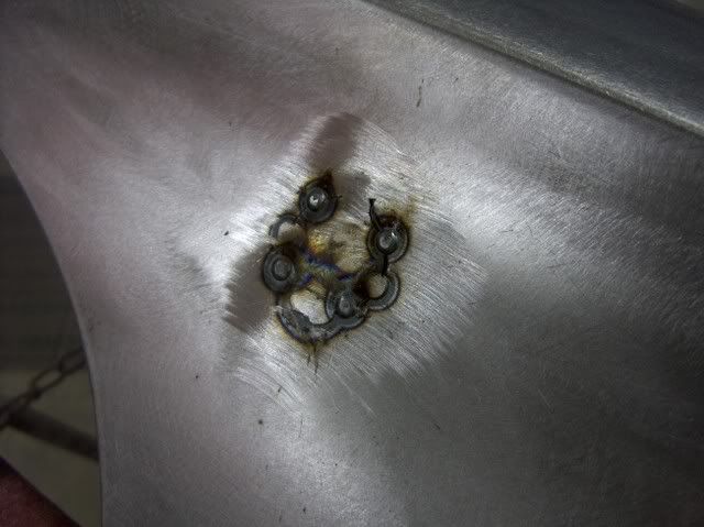
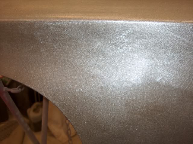
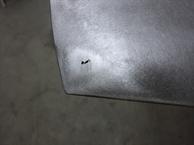
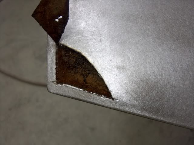
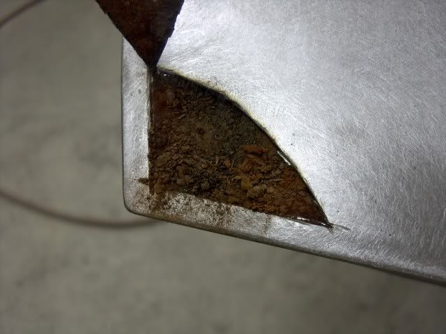
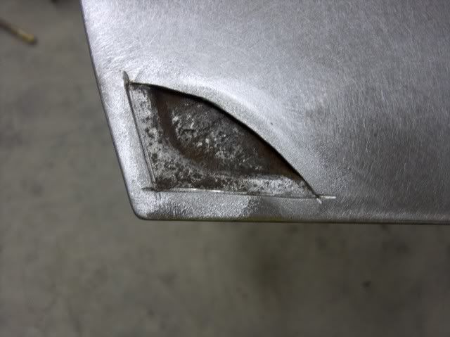
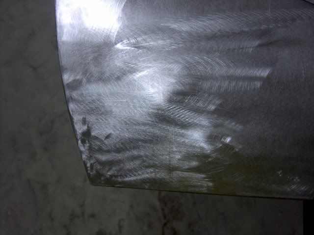
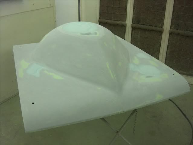
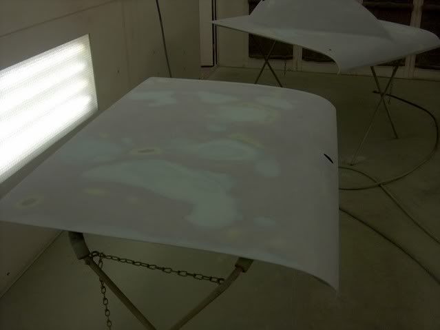
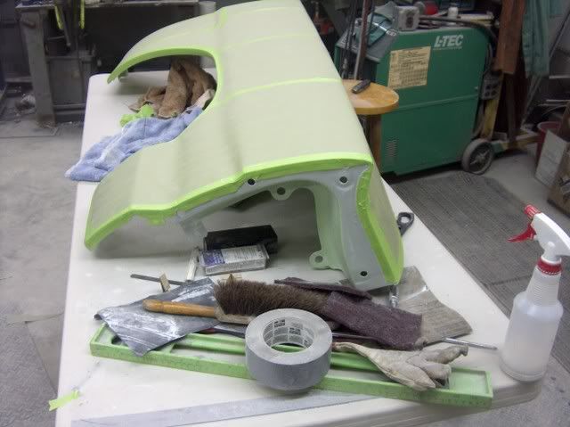
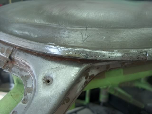
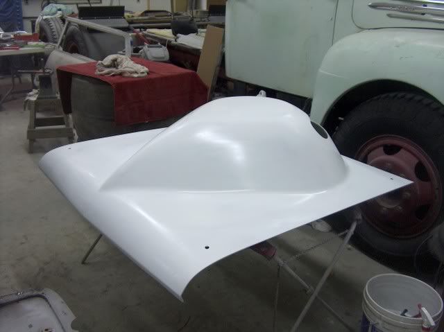
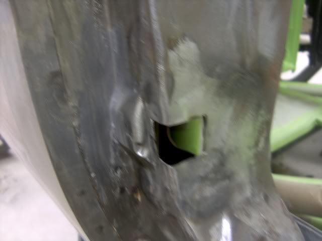
Starting to take shape. All the aluminum is removed, mat installed inside and out. A couple low spots and thin spots, as well as one really thin spot that looks like a hole!


Picture014.jpg


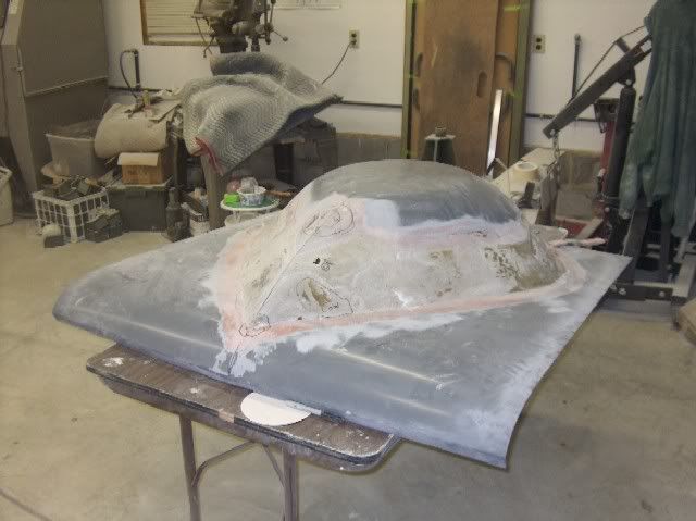
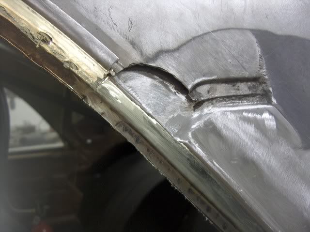
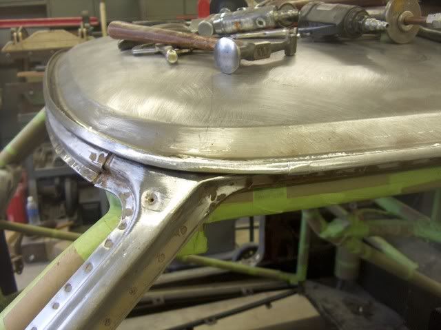
I think this might work yet!
 
Last edited:
To avoid these ads, REGISTER NOW!

David79z28

Well-known member
Joined
Jan 1, 2011
Messages
218
Location
North Texas
Great write up!! And that car is awesome. I love seeing cars that are out of the norm, even though I have a Camaro.
 

rt dak

Well-known member
Joined
Nov 16, 2010
Messages
714
Location
Putnam County, NY
Holy **** that's a tall hood. I've always hated those teardrop hoods but this just took it to the next level. :lol_hitti Car is nice though.
 
OP
M

MP&C

Well-known member
Joined
Oct 21, 2009
Messages
4,401
Location
Leonardtown, MD
Haha....yeah, it's been compared to Tip Oneal's nose before..

more progress on the hood.....


Picture001-1.jpg


A final smoothing with some evercoat 416, and ready for another test fit..


Picture021-1.jpg


Picture030.jpg


Next, as I was busy working on something else, the owner decided to try his hand at sanding the paint off the body. This was about June-July time frame, the sun was mercilous on his thinning topside, and after about a week using a DA outside in the heat, he found someone to media blast it. :bounce:


Picture029-1.jpg


This showed some areas in need of repair....


Picture031-1.jpg


Picture032-1.jpg


...a factory misfit (identical on two different 65's I've seen)


Picture061.jpg


Picture062.jpg


As he was anxious to go racing, he thought we should leave the door to cowl issue alone, but I assured him that a smoother, more streamlined fit would shave at least a second off his e.t. :)


So with a little cut here, and a slight bump downward, it was fixed to where the factory should have made it....


Picture064.jpg


Picture065.jpg


Picture067.jpg


Picture069.jpg


Much better.


Another area that needed attention was the lower front fender where the stainless trim had served as a nice moisture trap...


Picture070.jpg


Picture071.jpg


Picture072.jpg


Looking at the backside, notice the full penetration on the "dot" welds. If it's just sitting on top, there won't be anything left to hold once you grind things down smooth, so always check the back side to make sure the welder is set hot enough for a full penetration weld. Then they are planished, ground down, and repeat.....

Picture074.jpg


Picture077.jpg


Picture078.jpg


Picture084.jpg
 
OP
M

MP&C

Well-known member
Joined
Oct 21, 2009
Messages
4,401
Location
Leonardtown, MD
Moving back to the trunk area, the more you look the more you don't want to.
The channel for the weatherstrip seems to have sealed water in as well as out....


Picture167.jpg


It took a few weeks and a few phone calls, but there are still some good junkyard pieces available. We got the corner pieces out of a yard in CO. The rear channel across the trunk opening also has scattered pin holes, so I though I'd give a shot to bending some new ones. First, need a template:


Picture168.jpg


Picture169.jpg


That looks close enough. My press brake dies are only about 18" long, so I'll need to do this in three pieces. The middle one got put in first.


Picture171.jpg


Picture174.jpg


Be sure to check the back side for weld penetration:


Picture178.jpg


The replacement corner was cleaned up, the spot welds were ground off of the adjacent pieces to release the corner with no damage. Looks quite a bit better than the old one.


Picture175.jpg


Picture179.jpg


Picture182.jpg


Picture183.jpg


Picture185.jpg


Picture187.jpg


Picture188.jpg


Picture190.jpg


Well, on to the next corner. The driver's side was in sad shape:


Picture193.jpg


But in looking at the replacement, although in better condition, it did have issues of it's own.


Picture194.jpg


Time to break out the trusty Lancasters and make some replacement parts.


Picture196.jpg


The replacement corner was left attached to the quarter panel section it came with while remaking the channel in an attempt to maintain the shape.


Picture197.jpg


Note the sharpie "reference lines" in the next picture, to keep the bend in the correct location.


Picture198.jpg


Picture199.jpg


Picture200.jpg


Picture201.jpg


Picture202.jpg


Picture203.jpg


....And a comparison of the "new" part to the old one. That should do the trick!


Picture205.jpg
 
Last edited:
OP
M

MP&C

Well-known member
Joined
Oct 21, 2009
Messages
4,401
Location
Leonardtown, MD
Got the repaired piece all cleaned up in the sandblaster, and the car prepped for it to go in.


Picture206.jpg


Picture208.jpg


Picture209.jpg


Here's the plug weld holes drilled, ready for the welder to be fired up:


Picture210.jpg


Picture211.jpg


Picture212.jpg


Picture215.jpg


Picture216.jpg


There we go.....that should hold paint for awhile :D
 

rickairmedic

Well-known member
Joined
May 31, 2005
Messages
4,165
Location
louisville ,Ky
Robert as always fantastic work. I dont know if I can stay up late enough for the whole build though course not sure you will be up late enough to post it either :D.

Rick
 
OP
M

MP&C

Well-known member
Joined
Oct 21, 2009
Messages
4,401
Location
Leonardtown, MD
Thanks for the comments guys. One more for this evening, then we'll post some more tomorrow...


This area had a bit of bondo in it, always worth further investigation. Once removed, it showed the damage. This is a 1965 vintage, so probably lucky there isn't more to deal with than this. Someone's version of a previous repair involves banging in the rust holes and covering up the mess with body filler. We'll try to do one step better than that, install new metal.

Picture227.jpg


Here's the point of no return, hope I can bend up a replacement!


Picture228.jpg


Started off with a piece of steel, laid out the rough size and bend lines, then trimmed up a bit.....


Picture229.jpg


Picture230.jpg


Picture231.jpg


Made a new radius die to match the bottom bend on the original piece....


Picture232.jpg


Made some bends along both sides, not too much at first. Need to get in there with the Lancaster shrinker, which won't tolerate too much of a crease in the corner.


Picture233.jpg


Picture234.jpg


Picture235.jpg


Keep progressing along, bend a bit more, shrink some more, etc...


Picture236.jpg


Picture237.jpg


Once you have the basic shape, then use the shrinker along the wheel opening flange on front to get the same contour as the original. Then I used the large radius die again to add this same contour across the whole patch panel by giving a slight bend (real slight), moving about a quarter inch, repeat, etc.... The radius in the corner was trimmed slightly different from stock to provide a bit more room for the rear tires. The other side will be trimmed to match.


Picture238.jpg


Picture239.jpg


Installing the patch panel


Picture240.jpg


Picture242.jpg


Picture243.jpg


Picture245.jpg


Picture246.jpg


Much better!
 

Garys Garage

Well-known member
Joined
Nov 17, 2008
Messages
419
Location
il
You got skills, I will give you that. Nice metal work. Not feeling the hood. What was the second scoop for? Maybe painted it look right. Dont get me wrong I love a tear drop.
downsized_0911001508-1-1.jpg
 
OP
M

MP&C

Well-known member
Joined
Oct 21, 2009
Messages
4,401
Location
Leonardtown, MD
The hood had a 4" teardrop, the "scoop", bought separately, was 5". As the lower circumference is the same, this made the flat area up top considerably smaller, so it actually is less "bulbous" than had we kept the original scoop. Nice 64!
 
Last edited:
OP
M

MP&C

Well-known member
Joined
Oct 21, 2009
Messages
4,401
Location
Leonardtown, MD
For some reason, drip rails don't tend to like me. This is the second car in a row needing drip rail repairs.


Picture091.jpg


Picture088.jpg


Picture090.jpg


Using the cut-off wheel to grind/remove the spot welds.

Picture094.jpg


Dominoes, anyone?


Picture097.jpg


Picture100.jpg


Picture101.jpg


Looking at the rust just above the drip rail, it looks like it is up into the roof panel as well.


Picture102.jpg


The first order of business will be to remove the leaded seam to expose the lapped joint between the two panels. A soft flame on the acetylene torch and a wire brush makes short work of it.


Picture105.jpg


The closer I stay to the crease of the leading edge of the sail panel, the less the metal should move. A quick check of the back side shows that, although it will be tight, I can get a dolly in there. The top piece is marked a bit larger, to give room for welding and grinding the seam for the repair panel below it.


Picture106.jpg


An ice pick and a bit of grinding will show the extent of the damage, and let us know how far up we need to go for good metal. I did have to trim the top opening a bit more.


Picture107.jpg


....and before we get too carried away with the cut off wheel, let's mark some reference lines so the new piece will go back in the same spot.


Picture108.jpg


Opening up the tin can....also will need to grind away the spot welds holding it to the inner sail panel.


Picture109.jpg


Picture110.jpg


Picture112.jpg


In bending up the new piece, there needs to be a joggle just above the drip rail.


Picture115.jpg


The machine you see in the background here is actually what I should be using, but I think it would take longer to make the dies than what I have in shop time this evening.


Picture116.jpg


So we'll cheat, especially since I found a flat bar in the scrap pile just the right width.....


Picture117.jpg


Picture119.jpg


Picture120.jpg


Some hammer work on the welding table will reform the end, and then we can trim and test fit this piece. Still need to trim a bit more to match my reference marks, but it's real close. And as it's late, we'll have to put off welding until tomorrow.


Picture121.jpg


Picture122.jpg


Picture123.jpg
 
OP
M

MP&C

Well-known member
Joined
Oct 21, 2009
Messages
4,401
Location
Leonardtown, MD
It took a bit more trimming to get the measurements right to the reference line, and then the patch could be tacked in place.


Picture127.jpg


Picture128.jpg


Picture129.jpg


Picture130.jpg


Picture131.jpg


And then to fabricate the roof repair....


Picture132.jpg


Picture133.jpg


A hammer and large diameter punch will do wonders on a 2 x 4 block.


Picture135.jpg


Test fit:


Picture136.jpg


Well today was a good time for practicing bends for drip rails.

The last one I did for a 55 Chevy. A quick glance at the profile shows a slight kick up on the bottom just inside the face of the drip rail......


HPIM5196.jpg


Where my replacement came straight across the bottom...........


Picture105-1.jpg


Now I'll be the first to admit there's always room for improvement, and the gutter fabrication was one of them. I remembered the Pullmax Lockformer tooling I had bought off Ebay a couple years back. In looking at the tooling, I thought it may just work.


Picture138.jpg


I made a pass with a piece of scrap 18 ga................


Picture140.jpg


Marked and trimmed the top edge for the hem............


Picture141.jpg


Picture142.jpg


Picture143.jpg


The hem gets flattened out..........


Picture144.jpg


..........and is inserted headfirst into the apron brake. The apron clamps down just inside the tooling mark you see


Picture145.jpg


A finished sample, and comparison to the old original:


Picture146.jpg


Picture148.jpg


Yeah, I like that much better....
 
OP
M

MP&C

Well-known member
Joined
Oct 21, 2009
Messages
4,401
Location
Leonardtown, MD
Here's the final drip rail, complete with 3 clearance holes for the window weatherstrip screws and various plug welds.


Picture151.jpg


Picture152.jpg


Oops, still need to finish the roof patch!


Picture154.jpg


Picture155.jpg


Picture156.jpg


Test fit and installation of the drip rail:


Picture157.jpg


Picture159.jpg


Picture160.jpg


Picture164.jpg


Picture165.jpg


And there you have it.
 

rickey1013

Well-known member
Joined
Oct 29, 2009
Messages
103
Location
Hayward, CA
Great metal work can't get enough of that here. I like the car get tired of looking at all the regular picks for hot rods keep up the awesome post.
 
OP
M

MP&C

Well-known member
Joined
Oct 21, 2009
Messages
4,401
Location
Leonardtown, MD
Thanks for the comments.

After fixing the drip rail on the drivers side, the other side is already suspect for similar damage. The owner was hoping we could get by with leaving the passenger side alone. There was some deep pitting in the drip rail, and some visible where the seam sealer was removed. Found two small holes in the outer part of the drip rail, which I thought could be welded up if I had to........but where the inner part of the drip rail spot welds to the underside of the sail panel, I could feel the telltale signs. The metal had swelled up, giving the indication of some rust scale lurking between.


Picture035-1.jpg


Note pin holes:


Picture034-1.jpg


The owner really didn't want to cut this side open, so what's an ****-retentive guy with a bunch of raw sheet metal to do? So I waited for him to go on travel for work, called him up and then told him the bad news. :D


Picture037-1.jpg


Picture039-1.jpg


Replacement fitted and welded:


Picture040.jpg


Picture042.jpg


Picture043.jpg


Picture046.jpg


Picture049.jpg


Picture050.jpg


Picture052.jpg


Picture054.jpg


Picture056.jpg


There, all put back together, before he could protest too loudly ;)
 
OP
M

MP&C

Well-known member
Joined
Oct 21, 2009
Messages
4,401
Location
Leonardtown, MD
Working on getting the hood pins installed...... The goal was to finish up the body fitments and get the fenders, doors, hood and trunk lid all removed so their insides could be painted. The frame guy, Chris in Fredericksburg, had cut out the corners of the dash when installing the roll cage, and I trimmed the holes around the tubing a bit better, and finished welding where he couldn't get to when the windshield was still installed. The dash holes for the cage tubing will get some trim-lok edging to finish off the hole.

Picture058.jpg


Picture060.jpg


The owner had shown up about the time I finished the dash, and we got to work on the hood pins. I didn't want to just have an angle bracket screwed to the firewall, so I came up with these brackets out of 12 ga, they turned out nice and rigid! The front hood pins used the original holes in the core support that were for the hood pads.


Picture063-1.jpg


Picture065-1.jpg


Picture070-1.jpg


Hood drilled. Took some 7/16 bolts, ground a point and bolted in the hood pin holes to use as "spotters" for locating the holes in the hood.


Picture066-1.jpg


Picture067-1.jpg


Picture068-1.jpg


Now to concentrate on fixing 6 remaining pin holes :fingerscrossed:


Three above the wheel opening were easily filled with the mig, but the next three were about midway back on the rear quarter and about two inches up. Don't know where these came from, unless some bright individual had a rag stuffed down there to collect all the leaking rain water. All attempts to weld these holes just opened the holes much bigger, so i decided to cut a circle around the three and replace with some new metal.


Picture073-1.jpg


Now I'm not sure about what happened next, whether it was the domino effect, or just plain my luck. But when finishing off the welds of my patch, I noticed some of the telltale dark brown spots on the bottom side of the quarter. These are a tell tale sign of pitting working it's way through from the back side. Ice pick easily went thru, so I took the crud thug to the entire lower quarter on the inside to reveal the rest of them. Quite a bit of pin holes and deep pitting, so another hole was cut. The crud thug was used on the passenger side also, but it did not need any repairs. Whew!


Picture075-1.jpg


Picture077-1.jpg


Picture079.jpg


Picture080.jpg


In this repair I clamped everything up, started the weld from the back end, and just removed clamps as I went. This allowed the gap to close up for a nice tight fit for **** welding.


Picture081.jpg


Picture082.jpg


Inside view:


Picture083-1.jpg
 
OP
M

MP&C

Well-known member
Joined
Oct 21, 2009
Messages
4,401
Location
Leonardtown, MD
Noticed this was lurking while cleaning up the rear window channel, hoping to get a step closer to primer.


Picture252.jpg


Picture253.jpg


Picture254.jpg


The first step I normally take is to use the pick to check the surrounding area for any hidden damage, and decide how far to take the opening. Once you find solid metal, the next consideration is the ease of dressing out the repair. It's easier to grind and sand on an outside radius than an inside one, so that is factored into the cut size. Sometimes you don't have a choice, but best to make it easier on yourself when you can!


Picture255.jpg


Picture256.jpg


The channel is actually made in two pieces. The spot welds in the pinch weld area are removed from the top layer to remove the damaged pieces. The vertical piece actually travels down beyond the bottom of the window in this case, so that will be installed first. A new piece is cut out and bent to fit, and final sanding/grinding to get a tight weld joint.


Picture257.jpg


Picture258.jpg


Picture259.jpg


Picture260.jpg


The bottom piece has a radius in two directions, slopes up and in.


Picture261.jpg


Picture262.jpg


The outer (rear) radius was hammer formed after the shrinking and stretching was done. Then trimmed to fit and welded in place.


Picture263.jpg


Picture265.jpg


The inside corner joint was welded and cleaned up with a ball nose burr grinder, to keep water traps to a minimum.


Picture266.jpg


Picture267.jpg
 
Last edited:

mad57

Well-known member
Joined
Jan 30, 2009
Messages
1,698
Very nice attention to detail!!! great metal work...is it possible to see pics of the equipment you used to form this steel? I love this kind of tooling but from what i know these machines are huge and heavy and you need a huge amount of extra space... am i wrong? also is that 16 guage steel?
 
To avoid these ads, REGISTER NOW!
OP
M

MP&C

Well-known member
Joined
Oct 21, 2009
Messages
4,401
Location
Leonardtown, MD
We did run across more metalwork to fix prior to painting. The front fender had a hole for the antenna, which he didn't plan to use, so it was filled.


Picture285.jpg


Picture287.jpg


Picture289.jpg


The trunk lid hinges had been relocated inboard to clear the rear tubs, so the original holes were removed and filled.


Picture293.jpg


Picture294.jpg


Picture295.jpg


Picture297.jpg


And just when you're ready to load parts in the paint booth, this shows up:


Picture299.jpg


Wonder what caused that?


Picture301.jpg


Picture302.jpg


Picture303.jpg


Picture304.jpg


Picture306.jpg


Back sides primed (H/K KP-2):


Picture307.jpg


Front side primed, slick Sand high build, and guide coat (next day):


Picture314.jpg


Picture316.jpg


Hood all one color, it's starting to grow on me. :D


Picture317.jpg
 
OP
M

MP&C

Well-known member
Joined
Oct 21, 2009
Messages
4,401
Location
Leonardtown, MD
Very nice attention to detail!!! great metal work...is it possible to see pics of the equipment you used to form this steel? I love this kind of tooling but from what i know these machines are huge and heavy and you need a huge amount of extra space... am i wrong? also is that 16 guage steel?


Primarily automotive sheet metal is 19 GA from the factory. This size does not have a huge demand, so in some areas it is difficult to find. What you see me using for the repair panels is 18 GA, which is just slightly thicker. Here are some pics of what I use to make most repeir panels.....


Apron brake


Picture155.jpg


Jump shear


Picture180.jpg


Manual Press brake


Picture181.jpg


....and yes, these take up a bit of room, but these machines are "nice to haves" as most bends can be made up by clamping something to a bench and bending/hammering over an edge. There's quite a bit that can be done with simple hand tools and a bit of determination.
 

mad57

Well-known member
Joined
Jan 30, 2009
Messages
1,698
Thanks for the pics. I too have that pexto shear i just mounted it on rollers last night i also have my out rigers taken off as i mostly cut smaller pieces easier to store against the wall, Def my next piece will be some sort of brake iam so curious about those older northern freight 3 in one press/shear/roller combos, i know its cheaper but for what i do it would work. hers a pic of my pexto on skates.thank you.
 

Attachments

  • pexto on wheels.jpg
    pexto on wheels.jpg
    137.4 KB · Views: 73

mad57

Well-known member
Joined
Jan 30, 2009
Messages
1,698
Primarily automotive sheet metal is 19 GA from the factory. This size does not have a huge demand, so in some areas it is difficult to find. What you see me using for the repair panels is 18 GA, which is just slightly thicker. Here are some pics of what I use to make most repeir panels.....


I had gotten lucky a sun roof shop by me has tons of blanks or cut outs from installing sun roofs i usually shop there for my steel:) free or real cheap.
 
OP
M

MP&C

Well-known member
Joined
Oct 21, 2009
Messages
4,401
Location
Leonardtown, MD
Mad57, those three in one tools typically have one weak spot....the cheap cast arms on the sides. The first bit of overly exceeding the machines capacity and they tend to crack. I picked up the apron brake and shear you see for about 300 each at auction, so if you have the space, I personally would rather have older better stuff. :thumbup:

That's a good source for metal, and most of those will not have rust issues. Take all you can get!


A slight bit more progress, got the hood and trunk lid blocked out and low spots addressed. Will need a couple more coats of high build later this week as well as some of the few remaining bare parts. The doors and fenders look like they will get by with wetsanding only.


Picture319.jpg


Picture318.jpg


Picture321.jpg


I did have some help with sanding.


Picture085-1.jpg


One front fender left to sand, and then I'll spray another couple coats on the hood and trunk lid.


My nephew Chris did some prep work while I continued wet sanding, the rear tires were removed so we can trim a bit more inside the bottom edges of the wheel opening. We had a set of "painting grade" wheels and tires, but had to open up the bolt holes to accomodate the 5/8" studs. Also had to unbolt the bottom of the coilover shocks to get the rear tires off. Forgot how large those beasts were :eek:


Picture322.jpg


Picture324.jpg


Picture325.jpg


Picture340-1.jpg


The roll cage and chassis has been NHRA inspected, and we don't want any more paint on it that would interfere with weld inspections, so Chris masked off all the roll cage, and then he and Brad (the owner) cut and fit the padding to get it ready for the upholsterer. Here's the official "treasure map" to locate all the pieces.


Picture327.jpg


Picture335.jpg


Picture337.jpg


I had sprayed another couple coats of slick sand yesterday on the trunk lid as I still wasn't happy with it, and it turned out pretty nice this time. Started masking off the holes and front sides of the body panels, getting ready to spray some red on the back sides.


Picture343-1.jpg


Picture341-1.jpg


Picture344.jpg
 
OP
M

MP&C

Well-known member
Joined
Oct 21, 2009
Messages
4,401
Location
Leonardtown, MD
Got some painting done this evening, White sealer, Viper red base, and a couple coats of clear. Will let this sit for a few days and then get it prepped for spraying the outside.


Picture095-1.jpg


Picture096-1.jpg


Picture103-1.jpg


Picture104-1.jpg


Picture107-1.jpg


Picture106-1.jpg


Part of the job done by the frame builder was to cut out the opening for the new, larger, aluminum radiator. This was done with a plasma cutter, and still needed to be cleaned up a bit to straighten the edges. Here Chris is trying his hand at giving the opening in the core support some nice straight edges and radiused corners.


Picture353.jpg


Picture354.jpg


While he was tackling that as well as blocking the bare body to find low spots, I got a couple coats of white sealer on the loose body panels. It's an extra step, but I normally wet sand between this and the red base, as it prevents any stray dust nibs from appearing as little white dots when you wet sand and buff any imperfections later.


Picture357.jpg


Picture362.jpg


After the sealer and guide coat was sprayed, I started fixing some dents while Chris continued sanding.

This was about a 3 to 4 inch diameter bondo repair on the roof. Chris had sanded it out, so I got out the dent puller to try it's magic.


Picture364.jpg


Picture365.jpg


A little clean up afterwards with the hammer/dolly, and then a bit of sanding brings it right around......


Picture366.jpg


Picture367.jpg


We had a couple of "issues" left in the drip rail, namely a couple of scattered pin holes in the bottom that I thought I could fill with the mig. The first three went well. The last one, not so much. Here I thought I was done with this stuff!


Picture368.jpg


These holes were not visible prior to welding the pin hole in the bottom, but once the blue heat travelled up the side it appeared to stop there along the center in a jagged pattern. The trusty ice pick told the tale. I had a "practice" piece left over from my drip rail fabrication, so it came in handy. The damaged area was trimmed out, a replacement cut, and some shrinking done on the Lancaster to match the original.


Picture371.jpg


Picture374.jpg


All dressed up.....


Picture375.jpg


Picture376.jpg


........and back to where I thought I was two hours ago.....!
 

NUTTSGT

Super Moderator
Staff member
Joined
Sep 14, 2009
Messages
50,912
Location
Northern Central Ohio
Love the pics, it's going to look even better when finished.

I see a mount for a chute, the owner planning on running faster than 150 on a 9.90 index ? Or was it a matter of putting in on when the chassis was being built?
 
OP
M

MP&C

Well-known member
Joined
Oct 21, 2009
Messages
4,401
Location
Leonardtown, MD
The chassis is certified NHRA and IHRA I believe to 8.50...If I find out different, I'll post the info...


Got the hood wet sanded and test fit the Griffin radiator.......


Picture118-1.jpg


Picture120-1.jpg


Picture122-1.jpg


In addition to getting some more wet sanding done, (hoping to spray more red tomorrow) we had noticed a patch of lead in the B-pillar on the passenger side. Used the torch to melt it out, only to reveal a nice hole punched in. Judging from the direction the striking object must have travelled, it appears the door was not installed at the time. Looks like it had to be damaged and repaired at the factory??


Picture123-1.jpg


Picture124-1.jpg


Picture125-1.jpg


Picture126-1.jpg


Picture127-1.jpg


I've been told this was likely a "suspended" spot welder that was overzealously swung into the car at the factory?
 
OP
M

MP&C

Well-known member
Joined
Oct 21, 2009
Messages
4,401
Location
Leonardtown, MD
More painting done, basecoat:


Picture130-1.jpg


Cleared:


Picture132-1.jpg


Picture135-1.jpg


Picture136-1.jpg


Here's some progress on the body. H/K epoxy primer and then Slick Sand high build.


Picture148-1.jpg


Picture150-1.jpg


My nephew's contribution to the interior


Picture153-1.jpg


Full paint cans taped to the floor to help keep the air hoses out of the masking paper.


Picture154-1.jpg


Picture156-1.jpg


Picture157-1.jpg
 
OP
M

MP&C

Well-known member
Joined
Oct 21, 2009
Messages
4,401
Location
Leonardtown, MD
The car is blocked out, ready for the white sealer.


Picture159-1.jpg


Do these tires make my rear end look big?


Picture161-1.jpg


Here's the sealer painted. Even though I am using the 3M PPS on the paint gun, it was still a bit tight last time in painting the rocker panels. So we raised the car even higher in the air, and made use of some walk boards to get to all of the roof. Painted the roof first, and then moved the walk boards and finished the car.


Picture163-1.jpg


Picture165-1.jpg


I took these last two pictures as teaser shots for Brad (the owner). He had talked about painting the roof white, but this is as close as it gets. The Viper red is just too bright to have a white roof also.


Picture166-1.jpg


Picture169-1.jpg


Picture173-1.jpg


One more dose of wet sanding and it should be ready for red paint.


Picture180-1.jpg


Picture182-1.jpg


Picture183-1.jpg


Just to back up and offer some explaination here, I normally use a white sealer under the Viper red just to give it some more punch. The downside to this is if you were to get any dust nibs in the white that may not get noticed until after the red goes on, when the imperfections get buffed out you have a good chance of little white specs showing up in the bright red paint as the red gets rubbed off the white painted dust nib. This is why I usually do separate processes, wet sanding the white in between painting the red. One thing I noticed while spraying the white sealer was that it is a pain to get inside and paint the dashboard with the roll cage in the way. It was also a pain to get the underside of the rockers sprayed (let's use some jackstands) which made it fun to get to the roof (and now walkboards). Now all of this was fine for a sealer coat that was getting wetsanded anyhow, but I could just see me dragging an air hose across the door sill or opening at the quarter while trying to climb inside to paint the dash. Likewise, using walkboards on final paint, and having to move them between coats, was just an invitation for more debris in the paint. The early Fairlanes were known for having a chrome divider along the bottom of the sail panel, so I thought to use this as my saving grace, a break point to divide the paint job up into separate sprays. (like I need to drag this along further....:rolleyes: ) But in the interest of a better job, that's what we'll do. Here's the masking for painting the roof, dash, and front cowl. The car was placed back on the ground for easier access to the roof. Once the red has set up, we'll mask those areas, revert back to jack stands for access to the lower rockers, and spray again. Fun, fun.


White sealer wet sanded and masked:


Picture185-1.jpg


Picture188-1.jpg


Basecoat:


Picture190-1.jpg


Picture192-1.jpg


Cleared:


Picture194-1.jpg


Picture196-1.jpg


Picture197-1.jpg
 
OP
M

MP&C

Well-known member
Joined
Oct 21, 2009
Messages
4,401
Location
Leonardtown, MD
After waiting on my paint supplier a couple weeks (someone used up all his red tint :headscrat
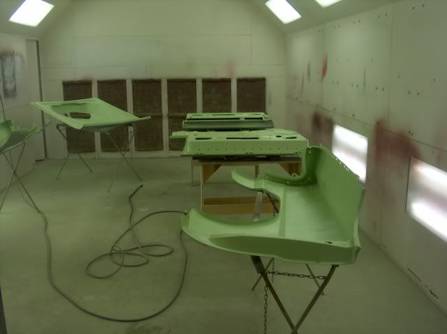
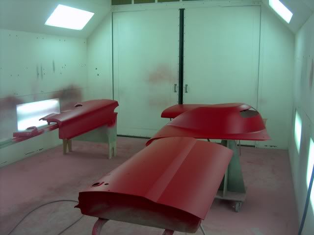
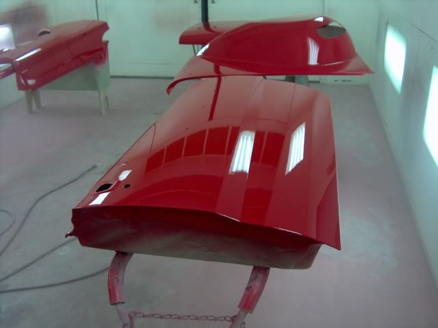
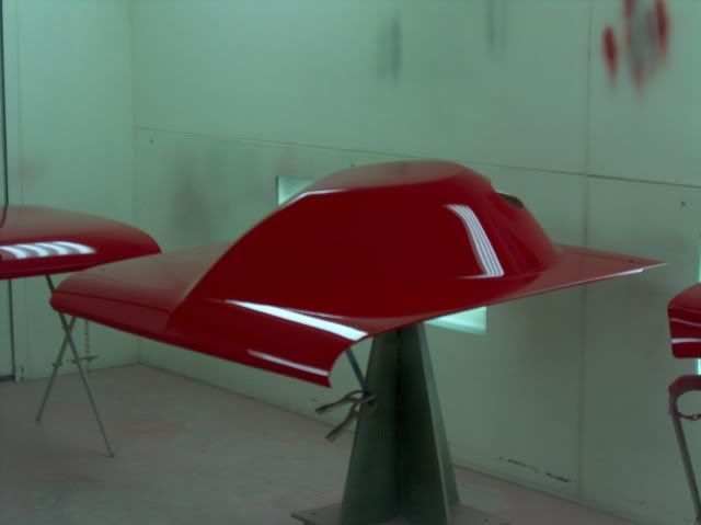
), here's more progress:


Base:

Picture215-1.jpg


Picture216-1.jpg


Cleared:

Picture218.jpg


Picture219-1.jpg


We'll let it set a few days before starting to wet sand and buff. We've got one rack of parts to spray Hot Rod black still.


Here is the car unmasked.


Picture221-1.jpg


Picture222-1.jpg


Picture223-1.jpg


Nephew Chris has started to reassemble some of the components, and has been touching up some of the black paint on the roll bar and tubs. We had our upholstery guy stop by a couple evenings last week to get the headliner knocked out. That goes in before windows, and I want the windows in before w/s & buffing so I don't sling too much inside.


Picture228-1.jpg


Picture227-1.jpg


Picture231-1.jpg


Tree freshener has lost some of it's kick, but it's still hanging in there......(+20 hp)
 
OP
M

MP&C

Well-known member
Joined
Oct 21, 2009
Messages
4,401
Location
Leonardtown, MD
Got some of the piece parts painted this morning, as well as the bottom of the hood, using SEM Hot Rod Black. I think there were some questions previously as to the amount of gloss, so hopefully this will help out.

The viewing window in the booth needs cleaning:


413817985_1434976093_0.jpg


Masking removed:

Picture387.jpg


Picture388.jpg


Picture389.jpg


Should dull out just a touch more, but seems a nice black to use for underhood sheetmetal.


We went to put windows in and the rear window had been damaged by some sand blasting, and Brad decided that while we were putting the window in, it may as well be a new one. We found a company that still makes the replacement rear window, and it showed up last week. We got the rear window and windshield in, so now we can start the buffing process on the body without slinging too much stuff inside.


Picture390.jpg


Picture397.jpg


Picture398.jpg


Got the tail light panel and roof buffed out today, will work on some more tomorrow. Then we can start re-installing the stainless trim.


Picture396.jpg


Picture399.jpg


Picture395.jpg
 
OP
M

MP&C

Well-known member
Joined
Oct 21, 2009
Messages
4,401
Location
Leonardtown, MD
Started putting stainless on. Sure makes a world of difference having polished it up, really looks nice against the red.


Picture405.jpg


Picture407.jpg


Picture412.jpg


Picture413.jpg


Picture414.jpg


Picture416.jpg


Picture426.jpg


Picture427.jpg


Picture428.jpg


Picture429.jpg


Still need to polish the aluminum trim around the rear window and Zoops that as well. Brad's not installing the wipers, so we found some chrome bolts and polished up some stainless washers to fill in the holes.


Picture431.jpg


Picture421.jpg


We ******* some loose ends on the car and got the rear wheels back on. Seemed like a nice day to roll it outside again for more pictures....


Picture434.jpg


Picture441.jpg


For what was considered a mid-size car back in the 60's this thing sure has some long quarter panels!
 
OP
M

MP&C

Well-known member
Joined
Oct 21, 2009
Messages
4,401
Location
Leonardtown, MD
We got the quarter windows installed, but while assembling all the pieces, noticed that one window was missing a felt "shoe"


Picture460.jpg


Picture475.jpg


The "shoes" are used to keep the rear corner of the window from flopping around so much when the window rolls down. So we used the one remaining as a pattern, a piece of the old window felt was recycled, and some .06 stainless tig wire duplicated the "factory" staple. These were originally held in with sheet metal screws, and as the holes were quite sloppy, rivet nuts were installed so we could use machine screws instead.


Picture464.jpg


Picture465.jpg


Picture466.jpg


Wheel tubs and no back seat quickly retired the old kick panels, so some new ones were cut out of .06 aluminum. Some trim lock finished off the edges.


Picture473.jpg


Picture474.jpg


Picture462.jpg


Picture477.jpg


The rear window trim (aluminum) had been polished up so Chris Zoop sealed and installed that as well.


Picture478.jpg


The tail lights and rear bumper were also installed. Getting closer all the time.


Picture479.jpg
 
OP
M

MP&C

Well-known member
Joined
Oct 21, 2009
Messages
4,401
Location
Leonardtown, MD
The "Fat" 460 really fills up the engine bay....


Picture233-1.jpg


All the components needed under the hood and no inner fenders to mount to make for challenging work. The radiator core support is filling quick.......


Picture237-1.jpg


.......and as we wanted to keep the other side open for fuse blocks and electrical relays, we had to look elsewhere for the overflow/vent tanks. Decided to make a bracket to clamp the vacuum pump tank to a section of the moly tubing of the frame. Once it was comleted, it was easy to see a simple modification would kill two birds with one stone.......


Picture238-1.jpg


Picture242-1.jpg


Picture244-1.jpg


Picture248-1.jpg


And DMV sent the tags the other day..... :D


Picture235-1.jpg


Starting on the electrical, everything from the switch panel, which mounts to the top cross bar of the roll bar.....


Picture493.jpg


.................and all the circuits from the switches go thru in line fuses, which will be mounted in the new glove box liner:


Picture483.jpg


The relay mounts above, and as you can see there are a couple extra spots pre-rivnutted in case we missed something. The wiring coming from the switches:


Picture485.jpg


The large red wire hanging in the above picture will feed the switch panel. The fuse panel for the main power inside will be mounted onto the glove box door, and another will be located on the radiator core support for engine components.


Picture487.jpg
 
OP
M

MP&C

Well-known member
Joined
Oct 21, 2009
Messages
4,401
Location
Leonardtown, MD
Starting to assemble the rest of the car.


Picture274-1.jpg


Fitting the front fender and stainless. Wax paper inserted under the stainless, one strip from below, one from on top. After all the tweaking is done with the panel fitment, the stainless is aligned one end to the other, remove the wax paper while holding the position, and snug in place. Helps to keep from scuffing up the new finish while fine tuning the stainless placement.


Picture280-1.jpg


Picture283.jpg


Pretty pleased with the door gaps. We'll see how well they stay that way once he get's racing....


Picture284-1.jpg


Picture285-1.jpg


Starting to take shape now!


Picture288-1.jpg


Picture289-1.jpg


Picture292-1.jpg


Still need to fine tune the gaps and tighten down the panels, then align the stainless down the sides.


Aligned the gaps on the front fenders, had to lower the core support slightly to close the door to fender gaps at the bottom. Aligned and tightened the stainless trim on the doors and front fenders, and installed the headlights. The low beams are the only ones hooked up, in case the return lane is dark....


Picture294-1.jpg


Picture295-1.jpg


Picture298-1.jpg


Picture299-1.jpg


Picture300-1.jpg


Picture301-1.jpg


Picture302-1.jpg
 
OP
M

MP&C

Well-known member
Joined
Oct 21, 2009
Messages
4,401
Location
Leonardtown, MD
Still polishing the grille, we'll get that in this weekend.


Is this enough clearance?


Picture304-1.jpg


Picture305-1.jpg


Got the grille and lower rocker moulding installed today.


Picture310-1.jpg


edit....here's the color difference with a REAL GOOD camera:


IMG_1950.jpg


IMG_1941.jpg


IMG_1954.jpg


IMG_1955.jpg


Still left to do..... final detail, wire loom in a couple places, and help load it up...


Picture500.jpg


Picture503.jpg


Picture504.jpg


Picture505.jpg


Battery is still up, time to go racing. We got him loaded up, and by 4 this afternoon he was headed for the test & tune at MIR in Budd's Creek.


Picture321-1.jpg


Picture509.jpg
 
Last edited:
To avoid these ads, REGISTER NOW!
Top Bottom