To avoid these ads, REGISTER NOW!

Can a Ingersoll Rand T30 have built in "bleed off" ?

mawrick

Well-known member
Joined
Nov 1, 2012
Messages
102
Location
Norway
Anyone know if the T30 (3000) IR might bleed itselfe of when it is stopped?.

And do I need to have a pipe going to an unloader valve?


Reason for wondering is that I have 2 of these old beasts sitting, but seem like ex the check valve is missing, and I'm not 100% sure how they have been sitting - I kinda think the 2 compressors have been working together in one way or another.


But basically what I'v been thinking about doing is:

Put a check valve on the line that goes into the tank, and have a pressure switch sitting on the tank, and I guess that's there this unloader would normaly route too, the tank already have a couple of what I belive to be safety valves - but one might be a what I'v seen described as "auxiliry valve" - and to my understanding this is used if the motor of the compressors are supposed to run all the time (mine won't).

If I dont route it to an unloader valve, will the compressor still bleed of the air that's between the compressor and the tank ? (outlet of the compressor)?.


If anyone have any tips - feel free to give tips (I'v gotten some tips here before regarding these in another thread - but thought I'd start a new thread with this question).


One last thing - would it do any harm to the compressor just to fire it up without being connected to a tank, or will it just blow the air out - and no damages done ?. (To test it)
 
To avoid these ads, REGISTER NOW!
OP
M

mawrick

Well-known member
Joined
Nov 1, 2012
Messages
102
Location
Norway
I converted a gas engine T30 to electric. Here is link to some pics of the configuration I set up to provide tank check valve, pressure relief valve and head pressure bleed-off:
http://sdwike.smugmug.com/Other/T-30/21621422_d8ncZP#!i=1759704295&k=9fs8NMr

Thnx - looks good :)

Is there big variation between the T30's configurations ? - as mine is this type:

12100022.jpg


But I guess the inner workings are the same ?

Any idea if I could have the unloader port on a check valve just routed directly to the pressure switch (which I will place on the tank, and only controlling the start/stop signal) - as the motors on this thing is quite big - 30HP.....)

Also any idea what size motor these would run on (smaller) - if I eventually change the motors.
 
Last edited:

Fixnair

Well-known member
Joined
Jan 5, 2013
Messages
476
Location
Sapulpa OK
There is no centrifugal pressure release on the 3000 series. You will need a check valve and pressure switch with unloaders valve on the side.
Yes you can run the compressor straight to atmosphere W/O damage.
A picture would be nice so I could see If the compressor has suction valve unloaders on it or not. The valve you might think is the auxiliary valve would probably have a toggle on top.
 

Provincial

Well-known member
Joined
Sep 21, 2011
Messages
6,874
Location
Near Salem, OR
At least some older gasoline-powered T30's had an unloader attached to the intake port that unloaded the compressor at a specified pressure. The gas engine kept running at full speed while unloaded.

Modern electric-powered versions have unloaders that act when the motor shuts down, and I think that there were several variations of these systems. There was even a system that kept the compressor running continuously when the average demand was greater than 80% of the compressor output.
 
OP
M

mawrick

Well-known member
Joined
Nov 1, 2012
Messages
102
Location
Norway
I'l take some better/more detailed pics of this and get back to you guys :)

(Will have to take a drive to get to the compressors, so I'l fix it next time I'm at the place).
 
OP
M

mawrick

Well-known member
Joined
Nov 1, 2012
Messages
102
Location
Norway
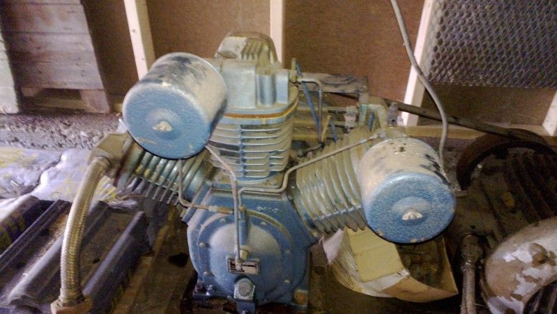
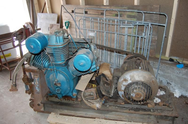
Here area few more pics of the way it stand today:

DSC_2008_zps741d294d.jpg


DSC_2012_zps455b65e3.jpg


DSC_2013_zpsaf3d4cc1.jpg


DSC_2014_zps2cb9cf31.jpg


some kind of valve:

DSC_2015_zpsebf14664.jpg


DSC_2016_zps03263787.jpg


DSC_2018_zps2c5b726e.jpg


DSC_2019_zpsd7705401.jpg


The other one looks much the same - but it's a bit older, I think made in 1959

DSC_2027_zps8b7a6efa.jpg


DSC_2021_zpsd67b959d.jpg


DSC_2023_zps587b36fa.jpg
 
OP
M

mawrick

Well-known member
Joined
Nov 1, 2012
Messages
102
Location
Norway
Bumping this thread as I'm still wondering if the pipes that goes to the top of the heads should be connected to a "pilot unloader valve"? (as one of the pipes goes out into free air as they sits now - not sure how this configuration have been where they was set up before).

Also could I set it up in a "dual control mode" - where one could switch it between continiouse running and start/stop mode?.


If I'v got thing right I presume what I would need to get this setup working is:

1x pilot unloader valve with a check valve where this is placed on the tank, hooked up to the outlet of the compressor and then hook up the coper line coming from the head to the "unloader part" of the valve ?. - and then it should "work" (in continious running mode)?.

Like this:

51u3NpsaVML.jpg


then add a pressure switch on the tank for the times I would want to run it in start/stop mode?.

From a youtube video - kind of the setup I'm thinking of:

kompressor_zps0adf2688.jpg


Any info about unloader valves etc that would fit these compressors would be appreciated - as the outlet is quite big as you can see from the braided line.

Also the pressure switch would eventually be used to control a star/delta switch to power the motor, so only acting as a "signal" - not running the current thru the switch.
 
To avoid these ads, REGISTER NOW!
OP
M

mawrick

Well-known member
Joined
Nov 1, 2012
Messages
102
Location
Norway
Read thru some of my other threads about similar subject, and I guess it's been answered there, about the unloader valve etc - but feel free to give some reccomendation about what/where to get parts that will fit my setup :)

thnx again
 
OP
M

mawrick

Well-known member
Joined
Nov 1, 2012
Messages
102
Location
Norway
Any idea what pressure they are set to by default? - and/or a way I can check the pressure it is set to operate at ?
 
OP
M

mawrick

Well-known member
Joined
Nov 1, 2012
Messages
102
Location
Norway
Have I understood this correct, and what I would need to set this up as a dual control unit:

compressor_dual_control_zps0f7e9b27.jpg


(just a quick "drawing" of what I think it should look like).

And what I would need is as follow:

1x electric pressure switch
1x pilot unloader valve
1x ball valve
1x in tank check valve
 

MTW

Well-known member
Joined
Aug 6, 2013
Messages
294
Location
SE Michigan
mawrick,

I'm going from memory from about 15 years ago when I last serviced one of these pumps.

If I recall correctly the check valve and unloader are built into the pump and not required externally.

The tank check valve was accomplished with the output disc valve in the high pressure head. I remember replacing a high pressure head, from the valve leaking tank pressure back through the valve. It was because the seat for the valve was worn and need to be machined, I replaced it instead of getting it machined.

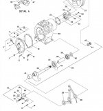
The unloader valve is a centrifugal one installed on the end of the crank like most pumps. The difference is that it's inside the case, not in an external housing like most units. You will see it in the attached breakdown of the case.
IR300 Crankcase.jpg

As to a constant run unloader I have never used the manual/pneumatic type as you are asking about. On my builds I always used a electric solenoid valve connected to the pressure switch for unloading during the constant run cycle. Along with a 3 position control switch for the operator Start Stop/Off/Constant Run

You can find the manual for the 3000 series pumps here:
http://www.irtechpubs.com/ir_pdfs/Compressed%20Air/Air%20Compressors/Reciprocating%20Compressor/SCD-475.PDF

And for other models here:
http://www.irtechpubs.com/index.cfm?fuseaction=view.main&type=Compressed%20Air&cat=206&sub=933

Hope that steers you in the right direction...
 
OP
M

mawrick

Well-known member
Joined
Nov 1, 2012
Messages
102
Location
Norway
So if I understand you correct I should be able to run this with an electric pressure switch and then hook up the line that goes back to the head into the "unloader" of the pressure switch ?.

And I wouldn't need a non return valve in the tank ?.


thnx again :)
 

MTW

Well-known member
Joined
Aug 6, 2013
Messages
294
Location
SE Michigan
So if I understand you correct I should be able to run this with an electric pressure switch and then hook up the line that goes back to the head into the "unloader" of the pressure switch ?.

And I wouldn't need a non return valve in the tank ?.


thnx again :)

You don't need a pressure switch with the unloader port. Run the head unloader to the centrifugal switch on the side of the crankcase, see the attached drawing showing the centrifugal unloader.

You don't need the tank check valve, the output valve in the head will hold back the pressure.

Download the manual for your unit from the link provided.
 
OP
M

mawrick

Well-known member
Joined
Nov 1, 2012
Messages
102
Location
Norway
Resurecting this one again :)

Haven't got time to do much to these yet (sadly) - but hopefully during this winter I'l have time again to look more info getting these things up and running again :)

At a Closer look it at least seem that one of them have what I think must be the Auxiliry valve:

IMG_20140926_141522_zps07142474.jpg


Can anyone confirm this is an AUX valve?

But this is not on the "newer" ones of them that I was thinking about using in the Garage (The other one will come to use at another location so don't want to take it off).

Where would one get such an AUX valve? (I presume the one that have been on the "blue" one must have been sitting on the tank that didn't come with thme).

Also - here is a valve that sat on the tank (they came with one tank) - is this just a safety valve?:

IMG_20140926_141639_zpsfbfb27df.jpg


And lastly - this one:

IMG_20140926_141422_zps97b8618c.jpg


Is this just the "safety valve" for cooler ? or is this some sort of AUX valve too ? (sits on the blue one).
 
To avoid these ads, REGISTER NOW!
Top Bottom